Advertisement
Quick Links
Preparing the Machine
1. Park the machine on a level surface.
2. Engage the parking brake.
3. Lower the loader arms.
4. Shut off the engine and remove the key.
5. Open the hood.
6. Turn the battery-disconnect switch to the O
7. Remove the rear cover; refer to the Operator's Manual for the machine.
© 2024—The Toro
®
Company
8111 Lyndale Ave So
Bloomington, MN 55044
Light Kit
Dingo® TX 1000 Turbo Compact Tool Carrier
Model No. 145-4544
Register at
www.Toro.com
Installation Instructions
position.
FF
Original Instructions (EN)
Printed in the USA
All rights reserved
3469-591A
*3469-591* A
Advertisement

Related Manuals for Toro 145-4544


Summary of Contents for Toro 145-4544
- Page 1 3469-591A Light Kit Dingo® TX 1000 Turbo Compact Tool Carrier Model No. 145-4544 Installation Instructions Preparing the Machine 1. Park the machine on a level surface. 2. Engage the parking brake. 3. Lower the loader arms. 4. Shut off the engine and remove the key.
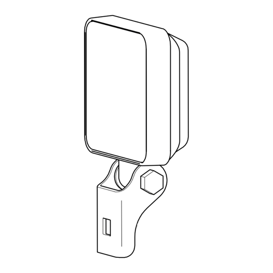
- Page 2 Installing the Front Light Parts Required Light Front bracket Bolt (5/16 x 3/4 inch) Nut (5/16 inch) Carriage bolt (1/4 x 3/4 inch) Nut (1/4 inch) 1. Install the front bracket to the frame on the left side of the control panel. Nut—1/4 inch (2) Carriage bolt—1/4 x 3/4 inch (2) G504763...
- Page 3 Installing the Rear Light Parts Required Light Rear bracket Bolt (5/16 x 3/4 inch) Nut (5/16 inch) Bolt (1/4 x 3/4 inch) Nut (1/4 inch) 1. Install the rear bracket to the frame on the right side of the machine. Bolt—1/4 x 3/4 inch (2) Nut—1/4 inch (2) G504789...
- Page 4 Routing the Wire Harness Parts Required Wire harness Switch Cable tie G341986s Machine harness connector Rear light Front light Accessory connector Switch 1. Remove the 2 bolts securing the relay bracket to the frame. Note: This provides extra clearance to route the wire harness. G508745 Page 4 3469-591 A...
- Page 5 2. Remove the plug from the left side of the control panel. From inside the machine, behind the relay bracket, route the front light connector through the hole and connect it to the front light. G508746 3. Remove the plug, route the switch connector through the hole, and connect it to the switch.
- Page 6 5. Connect the accessory connector to the accessory port (P02) on the machine wire harness. Note: Use the accessory connector from the kit wire harness to connect any other powered accessories. G508744 6. Use cable ties to secure the wire harness away from moving parts at the following locations: •...
- Page 7 • Main wire harness, behind the air cleaner Note: Coil any excess slack in the wire harness when you secure it to the main wire harness. G508959 • Rear light bracket G508960 3469-591A Page 7...
- Page 8 • Hydraulic hoses IMPORTANT Ensure that the wire harness is secured away from the radiator fan. G508958 7. Use the 2 bolts previously removed to secure the relay bracket to the frame. G508745 Page 8 3469-591 A...
- Page 9 Installing the Reflectors Parts Required Reflector Install the reflectors at the locations shown. G504820 Completing the Installation 1. Install the rear cover. 2. Turn the battery-disconnect switch to the O position. 3. Close the hood. 3469-591A Page 9...
- Page 10 Notes:...
- Page 11 Notes:...
Need help?
Do you have a question about the 145-4544 and is the answer not in the manual?
Questions and answers