Advertisement
Quick Links
XTCA
Operation Manual
CAUTION - Please read, understand, and follow all operating and safety instructions in this manual before using the tools and
controllers.
The XTCA controller is designed for exclusive use with specific Delta Regis XTA series drivers as defined in this manual. Do not
attempt to use the tools and/or controllers with any products other than as specified in this manual.
If you have any questions or concerns,
Please contact us at:
Delta Regis Tools, Inc.
7370 Commercial Circle
Fort Pierce, FL USA 34951
Ph +1-772-465-4302
Fx +1-772-465-4368
E-mail:
sales@deltaregis.com
Advertisement

Related Manuals for Delta Regis XTCA


Summary of Contents for Delta Regis XTCA
- Page 1 The XTCA controller is designed for exclusive use with specific Delta Regis XTA series drivers as defined in this manual. Do not attempt to use the tools and/or controllers with any products other than as specified in this manual.
- Page 2 10. Specific models of Delta Regis XTCA series controller are designated for use with XTA series screwdrivers as specified on the following pages. Use of the controller (or screwdriver) with any other screwdriver (or controller) may result in malfunction, damage, or injury.
- Page 3 XTCA Operation Manual Grounding - This controller (and AC power cord) is equipped with a 3-prong electrical receptacle/plug with ground pin. The controller must be connected to a properly grounded AC electrical outlet. Do not attempt to use this controller without a properly functioning ground connection.
- Page 4 XTCA Operation Manual Product Specifications Model No. XTCA1 Input Voltage 115 / 230VAC Input Frequency 50 - 60Hz Input Current 6.3A Output Voltage 40VDC Output Current 9A Max Output Power 360W Size (mm) 10.47 x 7.08 x 5.71” (266 x 180 x 145.1 mm) Weight (g) 8.99 lb (4080 g)
- Page 5 XTCA Operation Manual External Overview Touch Panel Bottom Panel Please do not use the MINI USB slot, as it is a reserved hole in Tool cable connection the original design and currently does not serve any function. Ethernet port RS232 Port...
- Page 6 XTCA Operation Manual Navigation Home - Operator Interface Delta Regis_XTCA_M_R0.0...
- Page 7 XTCA Operation Manual Navigation Home - Operator Interface (continued) Operator Interface Description 1. Job mode Normal / Advanced 2. Job name Displays the name of the job currently running Enable: Tool is ready 3. Driver status Disable: Tool not ready; the screwdriver’s red LED flashes 4.
- Page 8 Symbols Description Display screwdriver status, barcode, import / export, and function buttons Home Login password, normal settings, advanced settings, tool settings, controller settings, import settings, export settings, system settings, and calibration settings Setup Edit job and sequence switching Job & Sequence Display historic data, export data, import/export configuration files Data Graph...
- Page 9 XTCA Operation Manual Normal (Simple Job) Tree View Tree View displays the job name, sequence name and number of cycles (TR) Normal - Edit job Edit Job Setting Description Press this symbol to select all jobs After selecting one or more jobs, press this symbol to delete the selected job(s)
- Page 10 XTCA Operation Manual Normal - Add /Edit Job Edit job parameter Description Job ID Choose the Job ID - Range: 1-99, Default: 1 Supports capital and lower-case letters, numbers and symbols Job Name Range: 1-12 characters, Default: JOB-1 o: No completion signal (OK-JOB) export.
- Page 11 XTCA Operation Manual Off: Disable counting removed screws Reverse Count On: Enable counting removed screws Default: OFF The main page will display the screw removal torque value after setting the threshold torque value for screw removal touch. Rev. Threshold Tor.
- Page 12 XTCA Operation Manual Normal Job - Add Sequence Sequence parameter Description Edit job ID Display the selected Edit job ID. (The example in the figure shows JOB-1) Add sequence button, if there are more than 99 groups, this button will be grayed out and cannot be added more.
- Page 13 XTCA Operation Manual The processing method selected when the total number of screws in the Setting Sequence is counted to complete the action. OFF: The screwdriver won’t stop when the action is completed; nor will it affect the next start of the screwdriver.
- Page 14 XTCA Operation Manual Normal Job - Torque [14] Delta Regis_XTCA_M_R0.0...
- Page 15 XTCA Operation Manual Torque parameter Description Display the maximum torque of the tool and set the torque unit. Max Torque Default torque unit: Newton-meter (N-m) Display Sequence ID, (Range: 1~99, default: 1). Sequence ID Display Sequence name, (Range: 1~10 characters, default: SEQ-1) Sequence Name Set the target torque of the screwdriver.
- Page 16 XTCA Operation Manual OFF: Angle won’t stop immediately after timeout. Over Angle Stop ON: Angle will stop immediately after timeout. Default: OFF Upper range of Setting Angle. High Angle º (Range: 1~30600, default: 30600) Lower range of Setting Angle. Low Angle º...
- Page 17 XTCA Operation Manual Normal Job - Angle [17]...
- Page 18 XTCA Operation Manual Angle parameter Description Display the maximum torque of the tool and the set the torque unit. Max Torque Default torque unit: Newton-meter (N-m) Display Sequence ID Sequence ID default: 1) Range : 99; Display Sequence name Sequence Name (Range: 1~10 characters, default: SEQ-1) Set the target angle of screwdriver.
- Page 19 XTCA Operation Manual OFF: No CCW Pre-Run Unfasten. Pre-Run ON: CCW Pre-Run Unfasten. Default: OFF To set the speed (rpm) of pre-run, it must be set according to the speed range of the screwdriver specification and the required speed. If the set value exceeds the Pre-Run RPM specification, the screwdriver won’t start.
- Page 20 XTCA Operation Manual Edit job Setting Description After checking, select all the newly added jobs. Delete the selected jobs; it can delete single or multiple jobs. Copy the selected job together with the sequence and steps. (Single selection only) Job Count Display the current total number of Edit jobs.
- Page 21 XTCA Operation Manual OFF: The screwdriver won’t stop when the action is completed; nor will it affect the next start of the screwdriver. ON: When the lock is completed, the screwdriver will be locked Stop Job on OK immediately; user needs to press the "Confirm" key to confirm that the forward rotation can be released.
- Page 22 XTCA Operation Manual Advanced Job - Sequence Sequence Setting Description Display the previous page and click Edit job name. name Edit job (The example in the figure shows JOB-1) After checking, select all the newly added sequences. Delete the selected sequences; it can delete single or multiple selections.
- Page 23 XTCA Operation Manual Advanced Job - Add Sequence Sequence parameter Description Edit job ID Display the selected Edit job ID. (The example in the figure shows JOB-101) Add sequence button, if there are more than 50 groups, this button will be grayed out and cannot be added more.
- Page 24 XTCA Operation Manual Set the running time of a single screw. Timeout (Range: 0.1~60.0 seconds, default: 60 seconds) Save Save the settings on this page. Advanced Job – STEP STEP Setting Description Sequence Name Display the previous page and click Sequence name.
- Page 25 XTCA Operation Manual Advanced Job - Add Steps STEP parameter Description Edit job ID Display the selected Edit job ID. (The example in the figure shows JOB-101) Sequence ID Display Sequence ID. (The example in the figure shows SEQ-1) Add steps button, if there are more than 8 steps added, this button will be grayed out and cannot be added more.
- Page 26 XTCA Operation Manual Set the rotation direction of the screwdriver; Clockwise (CW)/Counterclockwise (CCW). Direction Default: Clockwise (CW). To set the speed (rpm) of screwdriver, it must be set according to the speed range of the screwdriver specification and the required speed. If the set value exceeds the Run Down Speed specification, the screwdriver won’t start.
- Page 27 XTCA Operation Manual Tool Tool Setting Description Remote start: Remote I/O control. Push: Push down to start the tool operation. Lever: Lever to start the tool operation. Both simultaneously: Trigger both push down and lever simultaneously to start the Start Setting tool operation.
- Page 28 XTCA Operation Manual Trigger the push-down to the set value to start the tool operation. (Range Push (%) 10%~90%, default: 50%) Save Save the settings on this page. Controller Controller Setting Description Setting of Controller ID. (Range: 1~255, default: 1)
- Page 29 XTCA Operation Manual Description Wired-Static/Wired-Dynamic. Default: Wired-Dynamic. Display the current IP of the controller. Set controller static IP. Default: 0.0.0.0. Set controller to connect to the default gateway IP. Default: 0.0.0.0. Set the port to connect to the server. (Range: 1~65535, default: 9000.) Set the export format of torque/angle data: Modbus Save the settings on this page.
- Page 30 XTCA Operation Manual Description Page 1 Mode Event Description Enable / Unfasten / Disable / Confirm / Clear Sum / Sequence Clear / Reset / Self Define 1 / Self Define 2 / Trigger-once Sensing / Switch Edit job (Nor 1~99,Adv 101~170).
- Page 31 XTCA Operation Manual Output Output Inquiry Description Edit job Select the Edit job. After checking, select all the newly added events. Delete the selected events; it can delete single or multiple selections. Copy the selected events. (Single selection only) If you choose to run the job, the Edit job parameter will be run uniformly; other parameters originally set will not act.
- Page 32 XTCA Operation Manual Output Setting Description Select event and time. Event: OK / NG / Over High / Below Low / Sequence Complete Signal / Job Complete Signal / Motor Signal / Start Signal / Unfasten / Self- Define 1 / Self- Define 2.
- Page 33 XTCA Operation Manual System - Permissions Password Setting Description New password Range 4~10 characters (support numbers only). Confirm password Range 4~10 characters (support numbers only). Save Save password s etting Function switch Description Set password for special functions, range 4-10 characters (support numbers only).
- Page 34 XTCA Operation Manual Page Block Description Click this button (black text on a white background) to disable switching between the Edit job/sequence icon. Switch Edit job/ Icon is grayed Sequence Click this button (black text on a yellow background) to switch between Edit job/sequence icon.
- Page 35 XTCA Operation Manual System - Screen Setting Screen Setting Description Set screen brightness; large number responds higher brightness. LED Brightness (Range: 1-7, default: 7) Save Save brightness setting. Set screen to rotate 180 . The controller will reset automatically to Screen Rotate apply the change.
- Page 36 XTCA Operation Manual System - System data System Management Description Factory reset default: Keep locked data, clear configuration files. Defaults Setting Resets Default: Restore factory default. Export Diagnostic Data Export system operation records, select source FTP / USB1 / USB2.
- Page 37 XTCA Operation Manual System - Update Firmware Update Description Controller Version Displays the controller version. Select the source: FTP / USB1 / USB2 containing the new firmware file. Source FTP upload file size limit: 500Mb File Select. The hex file to be uploaded (Example: BF01-0701-0-xxx.hex) Start Press to Start the firmware update.
- Page 38 XTCA Operation Manual Job & Sequence Switch Job Description Select Switch Job Select the job name to run. Job ID Displays the selected Job ID. OK Job Display whether the setting parameter is enabled for ‘Job OK’ signal. Display whether the setting parameter is enabled for ‘Stop on Job OK’...
- Page 39 XTCA Operation Manual OK Sequence Display whether the setting parameter enables ‘Sequence OK’ signal. Seq. Stop Displays whether the setting parameter enables ‘Stop on Sequence OK’. Timeout Display the parameter setting of timeout. Data - History Historic Data Description Select Display All / OK / NG Status.
- Page 40 XTCA Operation Manual Data - Export data Export Data Description Source Select the export source FTP / USB1 / USB2 Export Format Select the export format csv / zip (compressed). Select the start date (year/month/day), be sure to check the start Start date, it will be displayed next to "Start".
- Page 41 XTCA Operation Manual Data - Export/Import Configuration Export/Import Config. Description Select Export / Import Mode Select export/import source from FTP / USB1 / USB2. Source Limit of FTP upload file size: 500Mb Displays the current DB version. DB Ver. Select the import file. (extension.cfg) File Save the settings on this page.
- Page 42 XTCA Operation Manual Data - Graph Data Export Graph Data (USB) USB export graph data Single: Export one file at a time. Mode Default: Single Source Select the export source USB1 / USB2 Save Save settings on this page [42]...
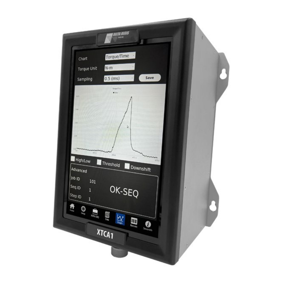
- Page 43 XTCA Operation Manual Graph [43]...
- Page 44 XTCA Operation Manual Chart Setting Description Select to display: Torque / Time: horizontal is Time, vertical is Torque. Angle / Time: horizontal is Time, vertical is Angle. Chart RPM/Time: horizontal is Time, vertical is RPM. Power/Time: horizontal is Time, vertical is Power.
- Page 45 XTCA Operation Manual Barcode [45]...
- Page 46 XTCA Operation Manual Barcode Setting Description After checking, barcodes. selects all Delete the selected barcode(s); You can delete single or multiple selections. Total Count Display the total number of barcodes. Display , No. button, barcode, from, number, and Edit job name.
- Page 47 XTCA Operation Manual Device Info [47]...
- Page 48 Displays the maximum rotational speed of the driver connected. Calibration Value Displays calibration value. Controller Information Description Controller SN Displays the serial number of XTCA. Controller Ver. Displays the controller version. MCB Version Displays the MCB version. Image Ver. Displays the Image version.
- Page 49 XTCA Operation Manual I/O - Output Control Functions Ordinary load Connector No Definition Description Inductive load OK: CN1 and CN2 are connected when a screwdriver is initiated. CN1 + CN2 are connected when short-circuited. 1+CN2 CN1 + CN2 are disconnected when open-circuit...
- Page 50 XTCA Operation Manual I/O - Input Control Functions Connector No Self-definition Description Example: When CN1 + CN2 is (CLOSE), screwdriver is initiated. CN 1 START IN When CN1+CN2 is (OPEN), screwdriver stops running CN 2 Start IN: Start Reboot: Restart...
- Page 51 XTCA Operation Manual Status Codes Code Error Message Description NO-ERR NO Error (display null value) ERR-CONT-TEMP Error controller temperature ERR-MOT-TEMP Error motor temperature ERR-MOT-CURR Error motor current too high ERR-MOT-PEAK-CURR Error motor peak current too high Error motor torque too high; the stop torque is greater than the "upper limit of ERR-HIGH-TORQUE judgment lock torque "...
- Page 52 XTCA Operation Manual System Messages Code System message Description INITIAL Initialization NORMAL NO Error (display null value) REMOTE-GPIO Remote control-IO REMOTE-LAN Remote control-LAN REMOTE-RS232 Remote Control-RS232 MODE-AUTO-LEARNING Mode - auto-learning MODE-ADV-TEST Pattern - advanced testing DISK-FULL Capacity is full WARN-DISK-FULL Warning capacity is almost full WARN-LAN-COMM.
- Page 53 Operation Manual Service The XTCA Controller is not user serviceable. Any repairs must be performed by a Delta Regis authorized service center. Please consult Delta Regis Tools for further information and the location of the nearest authorized service center. Repairs to power controllers must be performed by trained personnel, knowledgeable and qualified in the repair of power controllers.
Need help?
Do you have a question about the XTCA and is the answer not in the manual?
Questions and answers