Table of Contents
Advertisement
Quick Links
Advertisement
Table of Contents

Related Manuals for Elenco Electronics XK-550TK-B


Summary of Contents for Elenco Electronics XK-550TK-B
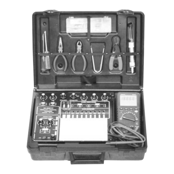
- Page 1 DIGITAL / ANALOG TRAINER MODEL XK-550K A COMPLETE MINI-LAB FOR BUILDING, TESTING AND PROTOTYPING ANALOG AND DIGITAL CIRCUITS Tools and meter shown not included. Assembly & Instruction Manual Elenco Electronics, Inc. Copyright © 1995 Elenco Electronics, Inc. Revised 1999 REV-F 753550K...
- Page 2 PS-550-B XK-550K POWER SUPPLY KIT (PS-550-B) PARTS LIST RESISTORS SYMBOL VALUE DESCRIPTION PART # R1, R2 120Ω 5% 1/4W (brown-red-brown-gold) 131200 1KΩ Pot PC MNT 192412 VR1, VR2 2KΩ Pot PC MNT 192421 100KΩ Pot PC MNT 192612 CAPACITORS SYMBOL VALUE DESCRIPTION PART #...
-
Page 3: Parts Verification
PARTS VERIFICATION Before beginning the assembly process, first familiarize yourself with the components and this instruction book. Verify that all parts are present. This is done best by checking off each item in the parts list. RESISTORS CAPACITORS SEMICONDUCTORS Diode Transistor INTEGRATED CIRCUIT Trim Pot... - Page 4 CONSTRUCTION Introduction Assembly of your XK-550 Digital/Analog Trainer Kit will prove to be an exciting project and give you much satisfaction and personal achievement. If you have experience in soldering and wiring techniques, then you should have no problem with the assembly of this kit. Care must be given to identifying the proper components and in good soldering habits.
-
Page 5: Power Supply Specifications
INTRODUCTION The XK-550K Digital/Analog Trainer is divided into four separate kits: BB-550-A, PS-550-B, AN-550-C and DG- 550D. Each bag of parts is clearly identified. Open only the kit called for in your procedure. DO NOT open any other bag at this time. The first kit is the BB-550-A which contains only the bredboard. The bredboard will be assembled to the front panel of the trainer during the assembly of the PS-550-B Power Supply. -
Page 6: Start Here
INSTALL COMPONENTS TO PC BOARD START HERE ê r S1 - 5-Pin Connector Bottom Left Corner of PC Board (see Figure A) r L-Bracket (see Figure B) r VR4 - 100KΩ Pot r VR3 - 1KΩ Pot (see Figure C) Top Left Corner of PC Board r S3 - 3-Pin Connector r S2 - 3-Pin Connector... - Page 7 INSTALL COMPONENTS TO PC BOARD Bottom Left Corner of PC Board START HERE ê r C11 - 100µF 25V (see Figure E) r R1 - 120Ω 5% 1/4W Resistor (brown-red-brown-gold) r C6 - .1µF Mylar (104) (see Figure D) r J28 - Jumper Wire (see Figure F) r J6 - Jumper Wire (see Figure F)
- Page 8 INSTALL COMPONENTS TO PC BOARD START HERE ê r VR1 - 2KΩ Pot r VR2 - 2KΩ Pot (see Figure C) r B1 - 4 Pin Bredblox r B2 - 4 Pin Bredblox r B3 - 4 Pin Bredblox r B4 - 4 Pin Bredblox (see Figure H) r C12 - 100µF 25V Lytic (see Figure E)
- Page 9 INSTALL COMPONENTS TO PC BOARD Bottom Right Corner of PC Board START HERE CONTINUE ê ê r C2 - 1000µF 35V Lytic r D1 - 1N4001 Diode r C4 - 1000µF 35V Lytic r D2 - 1N4001 Diode r D3 - 1N4001 Diode (see Figure I) r D4 - 1N4001 Diode r D5 - 1N4001 Diode...
-
Page 10: Mounting The Pc Board
MOUNTING THE PC BOARD Note: The holes in the two side panels have been punched differently. Be sure that you have the correct side panel when mounting them to the PC board. r Mount the PC board with four 4-40 x 1/4” screws (see Figure K). Do not tighten the screws. Figure K Note: From the foil side of the PC board, inspect the edges to be sure that there... - Page 11 Figure L MOUNT COMPONENTS TO THE SIDE PANELS Mount U1, U3 and U5 to the left side panel as shown in Figure N. Insert the pins of each IC into the holes of the PC board. Then, with the hardware shown in Figure M, attach each IC to the side panel. Solder the pins of the ICs to the PC board.
- Page 12 Mount U2 and U4 to the right side panel as shown in Figure Mica * Silicone Grease 6-32 x 5/16” Screw O. Insert the pins of each IC into the holes in the PC board. 6-23 Nut Then, with the hardware shown in Figure MA, attach each IC to the side panel.
- Page 13 HOW TO INSTALL CONNECTORS ONTO TRANSFORMER WIRES A connector will be placed in the primary wires of the transformer. This will allow you to remove the top panel from the trainer. Follow the procedures below. 1. Cut a six inch length off of each black primary wire. 2.
- Page 14 MOUNT COMPONENTS TO PANEL r Push the illuminated switch into the hole in the top panel with the lugs as shown in Figure Q. r Install the fuse holder with the side lug in the position shown in Figure Q. Fasten the fuse holder in place with the nut as shown in Figure R.
- Page 15 WIRE SWITCH AND FUSE HOLDER (see Figure U) Fuse r Slide the line cord bushing onto the line cord as shown in Figure U. r Spread the three line cord wires apart 6” from the end. r Strip the insulation off of both ends of the 6” red wire to expose 1/4” of bare wire. Pass the wire through the 1/2”...
- Page 16 RESISTANCE ANALYSIS OF POWER SUPPLY Static testing of the power supply circuits. Do not plug the power supply into the 120VAC power supply source until all resistance readings check out. The values given below are approximate. See Figure O for locations of testing points. Resistance From Circuit...
- Page 17 Locations for Testing Points Plug of line cord LM-7812 LM-7912 On test points 4 - 14 use the leads of the diodes. 5 pin connector right 5 pin connector -20 5 pin connector +20 5 pin connector left LM-7805 LM-317 LM-337 Figure O -16-...
-
Page 18: Fuse Replacement
VOLTAGE ANALYSIS OF POWER SUPPLY Proceed with the voltage analysis only if the resistance readings were satisfactory. Place the top panel on the unit. If any capacitors are inserted backwards, the panel will shield you if they explode. Make sure that the ON/OFF switch is in the OFF position. Plug the line cord into the 120VAC power source. -
Page 19: Power Supply Testing
POWER SUPPLY TESTING Plug the trainer into a 120VAC outlet and switch to the “ON” position (the power switch should light). With a dig- ital voltmeter, measure the voltage outputs at the power blocks. The +12V should measure between 11.4 and 12.6 volts. - Page 20 PROBLEM POSSIBLE CAUSE No voltage at negative variable output. 1. Measure for an AC voltage of 18VAC at cathode of D8, D10. A. Transformer and/or secondary connection to PC board defective. 2. Measure DC voltage of -28VDC at pin 2 of U5 LM337. 3.
-
Page 21: Final Assembly
FINAL ASSEMBLY If you are immediately going to build the remaining sections, do not continue with the instructions on this page and proceed to page 22. Knob r Fasten the front panel in place Nut 7mm with four #6 x 3/8” thread cutting Washer 8mm screws, as shown in Figure W. - Page 22 INSTALL COMPLETED UNIT INTO CASE r Latch the case lid down. Remove the protective backing from the case label. Stick the label in the depres- sion in the middle of the case lid. r Tie a knot in the line cord 12” from the switch. See Figure AA for the location of the line cord hole in the case.
-
Page 23: Circuit Description
CIRCUIT DESCRIPTION The power supply features two variable output voltages and three fixed 12V, -12V and 5V variable output voltages are 1.25V to 20V and -1.25 to -20V at up to 1 ampere maximum current. All supplies are regulated to better than .2V when going from no load to full load. - Page 24 In practice, the current through the diodes is not as shown in Figure 2C. Because capacitor C1 has a charge after the first cycle, the diode will not conduct until the positive AC voltage exceeds the positive charge in the A) Transformer capacitor.
- Page 25 2200µF REV-E Test Point...
- Page 26 QUIZ - POWER SUPPLY SECTION INSTRUCTIONS - Complete the following examination and check your answers carefully. 1. AC voltage is supplied to the rectifier stages by the . . . r A. step-up transformer. r B. step-down transformer. r C. 1 to 1 transformer. r D.
- Page 27 AN-550-C XK-550 ANALOG KIT (AN-550-C) PARTS LIST RESISTORS SYMBOL VALUE COLOR CODE PART # R14, R44 100Ω 5% 1/4W brown-black-brown-gold 131000 200Ω 5% 1/4W red-black-brown-gold 132000 R46, R47 330Ω 5% 1/4W orange-orange-brown-gold 133300 1KΩ 5% 1/4W brown-black-red-gold 141000 2KΩ 5% 1/4W red-black-red-gold 142000 R7, R11...
-
Page 28: Specifications
INTRODUCTION - ANALOG SECTION The Analog Section of your trainer contains a complete function generator capable of producing sine, square, and triangle waveforms. The frequency of this generator can be continuously varied from 1 hertz to over 100,000 hertz in five steps: 10, 100, 1K, 10K, and 100K. A fine frequency control makes selection of any fre- quency in between easy. -
Page 29: Start Here
INSTALL COMPONENTS TO PC BOARD START HERE CONTINUE ê ê r J9 - Jumper Wire r R5 - 200Ω 5% 1/4W Resistor (see Figure A) (red-black-brown-gold) r C25 - .0022µF (222) Discap r J8 - Jumper Wire (see Figure A) r J10 - Jumper Wire r R3 - 6.8KΩ... - Page 30 INSTALL COMPONENTS TO PC BOARD START HERE CONTINUE ê ê r B6 - 4 pin Bredblox r R48 - 22KΩ 5% 1/4W Resistor (see Figure F) (red-red-orange-gold) r D16 - 1N4148 Diode r Q1 - 2N3904 Transistor (see Figure G) (see Figure C) r R14 - 100Ω...
- Page 31 INSTALL COMPONENTS TO PC BOARD Figure H Mount down flush with Cut off START HERE PC board. The value ê may be marked on the back side of pot. Cut off excess lead r J18 - Jumper Wire length after soldering. (see Figure A) r R13 - 8.2KΩ...
- Page 32 RESISTANCE ANALYSIS OF ANALOG SECTION Static testing of the analog circuits. Do not plug in the power supply into 120VAC power source until all resistance readings check out. The values given below are approximated. SET SW3 TO SQUARE WAVE (refer to top panel From Circuit Ohms...
- Page 33 VOLTAGE ANALYSIS OF ANALOG SECTION Proceed with the voltage analysis only if the resistance readings were satisfactory. The values given below are approximate. The following measurements will be taken from the copper side of the PC board. Turn the unit on and place it upside down.
- Page 34 5. Set VR8 fully clockwise from the copper side of the PC board, and adjust the DC OFFSET knob until the meter reads 0 volts DC. 6. Set the meter to the 20 volts AC range and slowly turn VR8 counter-clockwise until the meter reads 5.5 volts AC.
-
Page 35: Final Assembly
FINAL ASSEMBLY If you are immediately going to build the remaining Figure K section, do not continue with the instructions on this page, proceed to page 35. Knob r Fasten the front panel in place with Nut 7mm four #6 x 3/8” thread cutting Washer 8mm screws, as shown in Figure K. - Page 36 CIRCUIT DESCRIPTION Functional Block Diagram The function generator frequencies are produced by an XR2206 AM Input integrated circuit. This IC is capable of producing high quality sine, Symmetry ADJ. Sine/Saw square and triangle waveforms of high stability and accuracy. The Output Multiplier output waveform can be both amplitude and frequency modulated...
- Page 37 SCHEMATIC DIAGRAM - ANALOG SECTION -36-...
- Page 38 DG-550-D XK-550 DIGITAL KIT (DG-550-D) PARTS LIST RESISTORS SYMBOL VALUE COLOR CODE PART # R36 - R43 120Ω 5% 1/4W brown-red-brown-gold 131200 220Ω 5% 1/4W red-red-brown-gold 132200 R16 - R19 1KΩ 5% 1/4W brown-black-red-gold 141000 r 16 R20 - R35 100KΩ...
- Page 39 USERS DESCRIPTION OF FRONT PANEL 1. OUTPUT TERMINALS - For all functions as stated. 4 pins per block. 2. TWO LOGIC SWITCHES - These are no bounce logic switches. Give one signal state change per move- ment of switch. 3. INPUT TERMINALS FOR LOGIC INDICATOR LEDs - “A” input corresponds with “A” lamp, etc. 4.
- Page 40 INSTALL COMPONENTS TO PC BOARD START HERE ê r R34 - 100KΩ 5% 1/4W Resistor (brown-black-yellow-gold) r R35 - 100KΩ 5% 1/4W Resistor (brown-black-yellow-gold) r R33 - 100KΩ 5% 1/4W Resistor (brown-black-yellow-gold) r R32 - 100KΩ 5% 1/4W Resistor (brown-black-yellow-gold) r R28 - 100KΩ...
- Page 41 INSTALL COMPONENTS TO PC BOARD START HERE ê r R43 - 120Ω 5% 1/4W Resistor (brown-red-brown-gold) r R42 - 120Ω 5% 1/4W Resistor (brown-red-brown-gold) r S5 - 4 pin connector (see Figure A) r R41 - 120Ω 5% 1/4W Resistor (brown-red-brown-gold) r R40 - 120Ω...
- Page 42 INSTALL COMPONENTS TO PC BOARD CONTINUE START HERE ê ê r D25 - LED and Spacer r U9 - 14-pin IC Socket r U9 - 74HC04 IC (see Figure B) (see Figure D) r J27 - Jumper Wire (see Figure C) r D24 - LED and Spacer (see Figure B) r D23 - LED and Spacer...
- Page 43 INSTALL COMPONENTS TO PC BOARD r SW4 - Slide Switch r SW7 - Slide Switch r SW10 - Slide Switch r SW5 - Slide Switch r SW8 - Slide Switch r SW11 - Slide Switch START HERE r SW6 - Slide Switch r SW9 - Slide Switch r SW12 - Slide Switch r SW13 - Slide Switch...
- Page 44 RESISTANCE ANALYSIS OF DIGITAL SECTION Place the top panel onto the unit. Static testing of the digital section circuits. Do not plug the power supply into a 117 volt power source until all of the resistance readings check out. The values given below are approxi- mate.
- Page 45 VOLTAGE ANALYSIS OF DIGITAL SECTION Plug the power supply into a 117 volt power source. The values given below are approximate. From Switch Position Volts Volts Measured In up position In up position less than 1V In up position In up position less than 1V In up position In up position...
- Page 46 TESTING THE DIGITAL SECTION TESTING THE LOGIC INDICATOR FUNCTION There are eight logic indicators which you will be checking out. Put a wire to the 5V power supply and touch the “A” logic indicator test pin. The “A” LED should light up. Remove the wire and the LED should go out. Do the same for the B, C, D, E, F, G and H pins.
- Page 47 FINAL ASSEMBLY r Fasten the front panel in place with four #6 x 3/8” thread Figure I cutting screws, as shown in Figure I. Knob r Fasten the PC board to the spacer to Nut 7mm the front panel with a fiber washer and a 4-40 x 1/4”...
- Page 48 INSTALL COMPLETED UNIT INTO CASE r Tie a knot in the line cord 12” from the switch location. Feed the line cord between the cross bracket and the PC board. r Locate the line cord hole in the case (see Figure N). Insert the line cord into the hole through the slot. To open up the slot, press down on one side of the slot (see Figure O).
- Page 49 CIRCUIT DESCRIPTION - DIGITAL SECTION THE DATA SWITCHES There are eight data switches labeled SW1 through SW8. The circuit is very simple. To perform the desired functions, there is a double throw double pole switch, wired as a single pole double throw. One end is connected to the 5V, the other to ground and the center lug is connected to the output.
-
Page 50: Schematic Diagram
SCHEMATIC DIAGRAM -49-... - Page 51 QUIZ - DIGITAL SECTION INSTRUCTIONS: Complete the following examination, check your answers carefully. 1. The logic switches consist of . . . r A. two NAND gates and an SPST switch. r B. three OR gates. r C. two NAND gates and a DPDT switch. r D.
- Page 52 Elenco Electronics, Inc. 150 W. Carpenter Ave. Wheeling, IL 60090 (847) 541-3800 Web Site: http://www.elenco.com e-mail: elenco@elenco.com...
Need help?
Do you have a question about the XK-550TK-B and is the answer not in the manual?
Questions and answers