Advertisement
Quick Links
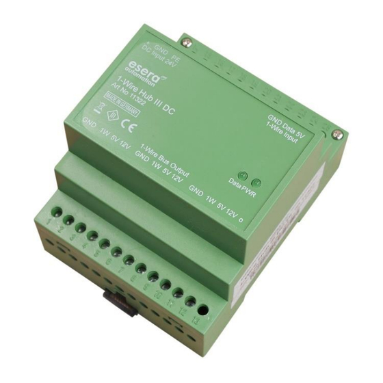
Art. No. 11322
USER GUIDE
1-WIRE HUB III DC
Central power supply for 1-Wire
ESERA Modules
18 – 36 VDC power supply (adapted to PLC typical 24
VDC)
Filtered power supplies for trouble-free bus supply
Top-hat rail case for switchboard assembly
Top-hat rail case, width 71 mm
Monitoring of output voltages and currents via 1-Wire
module
Screw-based connection
Easy to assemble
Energy efficient design with high efficiency
INTRODUCTION
1
Before you start assembling the 1-Wire Hub III DC and before you take the device into operation, please
read this assembly and operating instruction carefully to the end, especially the section referring to the safety
notes.
PRODUCT DESCRIPTION
2
The 1-Wire Hub III DC serves as the central power supply within a 1-Wire network. The 1-Wire Hub III DC is
providing the required bus voltage (5 V / 12 V) and also distributes the 1-Wire data line. The 1-Wire Hub III DC is
normally required only once in a network and is connected directly to a 1-Wire Bus Coupler or 1-Wire Controller.
Due to the input voltage range of 18 – 36 V, the device is ideally adapted to the system environment of PLC
controls, for 24 VDC supply.
To operate the 1-Wire Hub III, an upstream system power supply, providing the input voltage of 24 V, e.g. a DIN
rail power supply, is necessary.
The 1-Wire Hub III DC is equipped with a measuring function for the output voltage and current of the 5 V and 12
V output by default. This is measured by an integrated 1-Wire module (DS2450). Due to voltage- and current
measurements, issues with the supply of a 1-Wire network, such as overload or short circuit, may be detected at
an early stage.
The 1-Wire Hub III DC is designed for a broad supply range of 18 – 36 VDC (nominal 24 VDC).
As an "emergency power supply" for a 1-Wire network, the 5 V input voltage is provided in only one direction to
the output, even when there is no 24 V supply voltage available. This is to ensure a minimum function of the
1-Wire network, even in the event of failure of the 24 V main supply. In this operating mode the 12 V voltage is
not available.
Output power of the 1-Wire Hub III DC is designed to hold up to 40 modules.
All rights reserved. Reproduction as well as electronic duplication of this user guide, complete or in part, requires the written consent of
ESERA GmbH. Errors and technical modification subject to change. ESERA GmbH, ESERA-Automation 2025
www.esera.de
i
Network and all
11322 V2.0 R2.0 Manual
Page 1 of 8
Advertisement

Related Manuals for esera automation Auto-E-Connect 1-WIRE HUB III DC


Summary of Contents for esera automation Auto-E-Connect 1-WIRE HUB III DC
- Page 1 Art. No. 11322 USER GUIDE 1-WIRE HUB III DC Central power supply for 1-Wire Network and all ESERA Modules 18 – 36 VDC power supply (adapted to PLC typical 24 VDC) Filtered power supplies for trouble-free bus supply ...
- Page 2 8 devices of 1-Wire air quality sensors (11127) and 8 devices of 1-Wire 8-way switch modules (11220 (8x8A) or 6 devices of 11228 (8x16A)) can be connected. The device is designed for DIN top-hat rail mounting in a switchboard. AUTO-E-CONNECT® SUPPORT The ESERA Auto-E-Connect®...
- Page 3 Art. No. 11322 LED INDICATORS The module has different display LED`s. Please refer to the following table for their functions: LED status Description Function LED green Power Display for 5 V output voltage (if LED is lit, 12 V output voltage is available due to the system) ...
- Page 4 CONNECTION PLAN A connection plan and a connection example with further modules are available in our webshop. Pin assignment input, power supply, Bus Coupler/Controller 14 = plus supply voltage 15 = minus supply voltage 16 = grounding (PE) 23 = Ground 1-Wire input 24 = 1-Wire data line 25 = 5 V input from master (e.g.
- Page 5 Art. No. 11322 CONNECTION - EXAMPLE Example with 1-Wire Controller or 1-Wire Gateway, 1-Wire Hub III, Dual Digital Output and 8-fold digital input. All rights reserved. Reproduction as well as electronic duplication of this user guide, complete or in part, requires the written consent of ESERA GmbH.
- Page 6 OPERATING CONDITIONS The operation of the assembly group can take place only on condition of observing the required voltage and the ambient conditions. The operating position of the device is irrelevant. The device is meant to be used in dry and dust-free areas. If condensation forms, wait for at least 2 hours to acclimatise.
- Page 7 Art. No. 11322 All connection or wiring work must be carried out in a de-energized state. It is a fundamental safety measure that all connection and wiring work on electrical systems and devices should only be done when they are not live. Never work on electrical devices while they are powered. ...
- Page 8 WARRANTY ESERA GmbH warrants that the goods sold are free from material and manufacturing defects at the time of transfer of risk and have the contractually warranted characteristics. The statutory warranty period of two years from the date of invoice shall apply. The warranty does not extend to normal wear and tear. Claims of the customer for damages, e.g.
Need help?
Do you have a question about the Auto-E-Connect 1-WIRE HUB III DC and is the answer not in the manual?
Questions and answers