Table of Contents
Advertisement
Quick Links
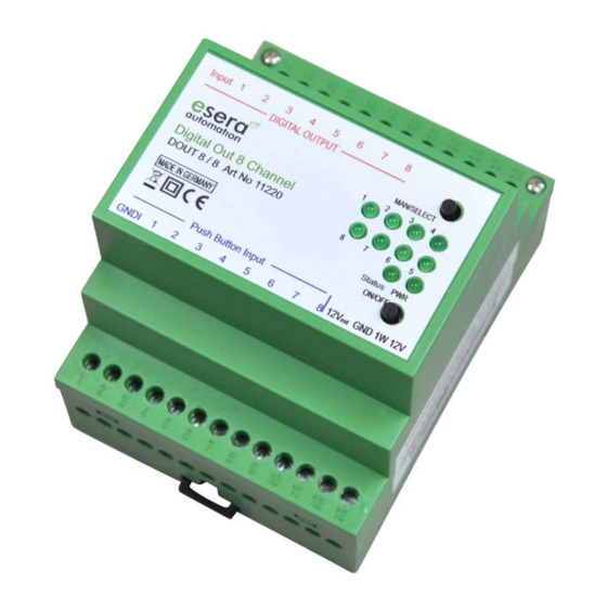
Art. No. 11220 V2
8-Fold Switch Module with Button Inputs
8 power relays with 8 A continuous power
Control inputs for button and 1-Wire Bus
LED indicator for activated relays
Switching of direct power consumers or
alternative power consumers, e.g. lighting,
heating or sockets
Top-hat rail cases for switchboard assembly
Easy software-based control
Low space requirement in switchboard
Easy to assemble
1
Introduction
Before you start assembling the 8-fold Switch Module and put the device into operation, please read this
assembly and operating instructions carefully to the end, especially the section referring to the safety notes.
2
Product description
With the
8-Fold Switch Module
with an output of up to 8A continuous power.
The switch module can be controlled directly by an external button (e.g. light switch) or by button-menu on the
module top side, independent of the 1-Wire interface For switch operation only 12 V power is required. Thus, a
high reliability, e.g. for switching of lightings, outlet circuits or other consumers can be reached, even in case of a
breakdown of a central control / software.
To operate the switch module we recommend the use of one of our 1-Wire Hub modules.
3
Technical data
Switching channels:
Switching voltage:
Switching power/Power: Maximum 8A continuous power per output and maximally 1840VA continuous power
Fuses:
Data interface:
1-Wire Component:
Supply voltage:
All rights reserved. Reproduction as well as electronic duplication of this user guide, complete or in part, requires the written consent of
ESERA-Automation or E-Service GmbH. Errors and technical modification subject to change. ESERA-Automation, E-Service GmbH 2018
www.esera.de
User Guide
for 1-Wire Bus
it is possible to connect direct power consumers and alternative power consumers
8, changeover relay (NO contact)
Maximally 250V direct power voltage or alternative power voltage
in case of Ohm resistive load.
Minimum load 10mA
Maximum 10A power in total for all outputs
In case of capacitive or inductive loads, appropriate additional wirings, e.g. spark
suppressor capacitors must be considered. Maximum power and output will be reduced.
External preliminary fuse with 10A recommended
1-Wire Bus (12V, data and load)
DS2408 (8-Fold I/O)
12VDC (+/-10 %)
11220 V1.0_R1.1 Manual 8-Fold Switch Module
Page 1 of 6
Advertisement
Table of Contents

Related Manuals for esera automation 11220 V2


Summary of Contents for esera automation 11220 V2
-
Page 1: User Guide
Art. No. 11220 V2 User Guide 8-Fold Switch Module with Button Inputs for 1-Wire Bus 8 power relays with 8 A continuous power Control inputs for button and 1-Wire Bus LED indicator for activated relays Switching of direct power consumers or alternative power consumers, e.g. - Page 2 Power consumption 12V:Idle mode, no output relay active: ca 10mA All output relays active: ca 160mA Button interface: 8 digital inputs, pulse input, for instance, for button or motion detector (make contact) Pulse duration of at least 40ms Input power 10-30VDC, maximum 10mA per input, common load. Inputs insulated with respect to the 1-Wire interface and power supply Connection: Screw terminals (up to 2,5qmm wire cross section)
- Page 3 The impulse control, comparable to a staircase lighting timer, allows any number of light sensors and motion detectors to be connected at the same time. Further details on the ESERA automation lighting system can be found on the following website: https://www.esera.de/smart-home/anwendungsbeispiele/lichtsteuerung/ All rights reserved.
- Page 4 Apart from light buttons, any other pulse control signal can be used to trigger the outputs. All three interfaces, the manual control mode interface, the 1-Wire interface as well as the button interface, work in parallel on the outputs. For instance, a via the 1-Wire interface triggered output can be switched on or off either manually or with button interface.
- Page 5 Art. No. 11220 V2 Relay Output: Output 1 = 1, Output 2 = 2, Output 3 = 4, Output 4 = 8, Output 5 = 16, Output 6 = 32, Output 7 = 64, Output 8 = 128. Data Output: 1_OWD1_1|8 =>...
- Page 6 Devices that are to be operated at a voltage greater than 35 VDC / 12mA, may only be connected by a qualified electrician and put into operation. Commissioning may only be realized if the circuit is built into a contact proof housing. ...
Need help?
Do you have a question about the 11220 V2 and is the answer not in the manual?
Questions and answers