
Related Manuals for Optimus OPT-CA-211 Series


Summary of Contents for Optimus OPT-CA-211 Series
- Page 1 Product Manual Combi Actuator OPT-CA4-211 OPT-CA8-211 OPT-CA12-211 OPT-CA16-211 OPT-CA20-211 OPT-CA24-211...
- Page 2 Product Manual | OPT-CAx-211 Table of Contents 1 Product Description ............................5 1.1 Product Models .................................... 5 1.2 Mounting and Connection Diagrams ..........................6 1.3 Technical Specifications ................................8 2 Manual Operation ............................9 2.1 Changing the Basic Operating Function of the Device ....................10 2.2 Control By Function Blocks ..............................10 3 Device Parameters ............................11 3.1 General Parameters ...................................11...
- Page 3 Product Manual | OPT-CAx-211 4.4.8 Hyteresis ....................................28 4.4.9 Fan Speed Data Type ...............................29 4.4.10 Fan Speed on Startup ..............................29 4.4.11 Fan Speed Bus Voltage Fail ............................29 4.4.12 Window Contact Action ...............................30 4.5 3-Speed Fan Coil ..................................32 4.5.1 Fan Start Delay ...................................32 4.5.2 Fan Acceleration Time ..............................32 4.5.3 Fan Speed Output ................................33 4.5.4 Fan Speed Change Delay ...............................33...
- Page 4 The agreed specifications are final for all orders placed. OPTIMUS SOLUTIONS accepts no liability in any way for possible errors or possible deficiencies in this document. OPTIMUS SOLUTIONS reserves all rights in this document and in the subjects and drawings contained herein.
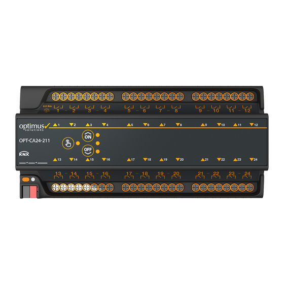
- Page 5 Product Manual | OPT-CAx-211 1 Product Description The OPT-Caxx-211 is a KNX compatible automation device that combines different usage purposes. Switch/Valve, Shutter/Blinds, 3-Point Motor and Fan Coil control operations can be performed on a single device. There are models with 4,8,12,16,20 and 24 switch outputs. Each switch contains a latching type relay with independent power supply and capable of handling up to 16A of current, responding to inrush request.
- Page 6 Product Manual | OPT-CAx-211 1.2 Mounting and Connection Diagrams Combi actuators are designed to be mounted on a switchgear type DIN rail. Due to the hidden spring mounting, there is no need to pull a latch to disassemble it: to mount the device on the rail, you only need to place the upper part first and push the lower part towards the rail until you hear the click.
- Page 7 Product Manual | OPT-CAx-211...
- Page 8 Product Manual | OPT-CAx-211 1.3 Technical Specifications Supply Voltage KNX 30 VDC KNX Current Consumption Max. 10mA KNX mode S-Mod Connection KNX Connection Protection Class IP 20 Mounting DIN Rail Number of Output 4, 8, 12, 16,20 or 24 Switching Current 16A 277 VAC -5...+45 °C Operation...
- Page 9 Product Manual | OPT-CAx-211 2 Manual Operation The device is programmed to connect all channels to the Shutter/Blinds as factory settings. It is also loaded to control the Shutter/Blinds in manual adjustment. However, if desired, all channels can also be set as contact modules(!). In order to make manual controls of the device, the KNX connection must be made and the line must be active.
- Page 10 Product Manual | OPT-CAx-211 2.1 Changing the Basic Operating Function of the Device The device is fabricated and programmed to control all channels as Shutter/Blinds. However, if desired, this feature can also be changed so that all channels are switches(for security reasons, this feature is not allowed on programmed devices).
- Page 11 English will be it. Below is the explanation with the English menu. The Optimus Combo Actuator series is collected in a single library file (knxprod). You can download the current version of this file from our website. Once we have added the library file to the ETS project we can start editing its settings: 3.1 General Parameters...
- Page 12 Product Manual | OPT-CAx-211 3.1.1 Start Up Delay When the device is energized, it is the area where the time to wait to start performing the boot operations and sending the current status information is determined. It is used to spread the overall take-off requests of the entire system over time.
- Page 13 Product Manual | OPT-CAx-211 3.2 Channel Configuration The Second and Last Tab of General Settings is the Channel Configuration. In this section, functions are assigned to the channels. Assignments are repeated in quartet channels. Shutter/Blinds: Uses two switches, the other two are the same, “3-Point Controlled Valve” or “Switch” can be selected. Switch: Uses 1 output, FB2 is designated as Shutter/Blinds if FB1 switch is selected, for the other two switches, “Shutter/Blinds”, “Switch”...
- Page 14 Product Manual | OPT-CAx-211 4 Device Functions 4.1 Switch Parameters It is the function that makes 1 output open circuit or short circuit according to the incoming command. The parameters are shown below: 4.1.1 Output Type It is where the natural principle of operation of the output switch is defined. The default value is Normally Open. When the ON command is received by the channel, the switch is short-circuited, when the OFF command is received, the switch is open circuit.
- Page 15 Product Manual | OPT-CAx-211 4.1.4 Receive Data in 8-bit A setting for the switch to change position by 1-byte as well as by 1-bit. It is generally used to control heating/cooling valves that work with thermostats that send 1-byte values. When marked as "Yes", the Threshold value is determined by the line that opens.
- Page 16 Product Manual | OPT-CAx-211 4.1.8 Time Function It is the part where the switch is set to perform time-dependent operations. If the transactions related to this are to be carried out, "Yes” is selected. In this case, a tab called "Time Function" is formed under the Switch Parameters in the middle tab.
- Page 17 Product Manual | OPT-CAx-211 Common Object : Object Function Length / Data Type Channel Number 10 : Channel - 1 20 : Channel - 2 30 : Channel - 3 40 : Channel - 4 50 : Channel - 5 60 : Channel - 6 70 : Channel - 7 80 : Channel - 8...
- Page 18 Product Manual | OPT-CAx-211 Common Object : Object Function Length / Data Type Channel Number 12 : Channel - 1 22 : Channel - 2 32 : Channel - 3 42 : Channel - 4 52 : Channel - 5 62 : Channel - 6 72 : Channel - 7 82 : Channel - 8...
- Page 19 Product Manual | OPT-CAx-211 Common Object : Object Function Length / Data Type Channel Number 14 : Channel - 1 24 : Channel - 2 34 : Channel - 3 44 : Channel - 4 54 : Channel - 5 64 : Channel - 6 74 : Channel - 7 84 : Channel - 8...
- Page 20 Product Manual | OPT-CAx-211 • Switch: Used to make the switch short-circuit or open-circuit with the 1 bit value given by this object. • Switch Status: This object shows the position of the switch with the 1 bit value. • Switch Threshold Input: Used to make the contact short-circuit or open-circuit with the 1 byte value through this object •...
- Page 21 Product Manual | OPT-CAx-211 4.2 Shutter / Blinds Shutter or blinds are controlled through 2 switches. The important thing to note is that only one output is allowed to be activated in any given position. The device performs this process programmatically. Since the shutters operate two switches, the odd-numbered switches in the upper row should be connected in the direction of opening the shutter, and the double-row contacts in the lower row should be connected in the direction of closing the shutter.
- Page 22 Product Manual | OPT-CAx-211 4.2.3 Act with Central Blind Object It is an option for the shutter function to move with communication objects number 4 and 5 as well. If desired, it is necessary to select "Active". 4.2.4 Scenes Used to determine the positions that the Shutter/Blinds will take based on 1byte Scene commands. When the Scenarios option is selected as "Yes", a tab called "Scenes"...
- Page 23 Product Manual | OPT-CAx-211 The communication objects of an example Shutter/Blinds function are as follows: Common Object : Object Function Length / Data Type Channel Number 10 : Channel - 1 ... 2 30 : Channel - 3 … 4 50 : Channel - 5 …...
- Page 24 Product Manual | OPT-CAx-211 Common Object : Object Function Length / Data Type Channel Number 13 : Channel - 1 ... 2 33 : Channel - 3 … 4 53 : Channel - 5 … 6 73 : Channel - 7 … 8 93 : Channel - 9 …...
- Page 25 Product Manual | OPT-CAx-211 4.3 3-Point Valve Motor These valve motors receive commands from different inputs (Shutter/Blinds alike) to direct the fluid flow or to off the fluid. Since these valve motors use two switches, the odd numbered switches in the upper row must be connected in the direction of opening the valve and the double numbered switches in the lower row must be connected in the direction of closing the valve.
- Page 26 Product Manual | OPT-CAx-211 The communication objects are as follows. Common Object : Object Function Length / Data Type Channel Number 10 : Channel - 1 ... 2 30 : Channel - 3 … 4 50 : Channel - 5 … 6 70 : Channel - 7 …...
- Page 27 Product Manual | OPT-CAx-211 4.4 Fan Coil with 2 Speed Fan coil devices are mechanical devices used in heating and cooling systems that provide air conditioning in the space from the conditioned liquid passing through them. Inside the device there is an engine for air circulation. This engine has different levels of speed.
- Page 28 Product Manual | OPT-CAx-211 4.4.3 Fan Speed Output There are two types of progressive operation. The first and common one is the model, in which one single output is activated for each stage, while the others are made open contact. So for low fan speed, the first speed output is On, the others are Off;...
- Page 29 Product Manual | OPT-CAx-211 4.4.9 Fan Speed Data Type At fan speeds, the data type is 1-byte and can be published in two formats. The first of these is the DPT 5.100 data type, which is listed as 0,1,2. The desired or current fan speed is indicated by these figures. The other data type is DPT 5.001.
- Page 30 Product Manual | OPT-CAx-211 4.4.12 Window Contact Action The 1-bit ON command that can come from the KNX line to the "Fan Coil Window Contact" communication object transmits the information that the window / door has been opened to the device. This information gives the device the possibility to manually readjust the fan speed.
- Page 31 Product Manual | OPT-CAx-211 Common Object : Object Function Length / Data Type Channel Number 16 : Channel - 1 ... 2 56 : Channel - 5 … 6 96 : Channel - 9 … 10 136 : Channel - 13 … 14 Fan Coil On/Off Status 1 bit / boolean 176 : Channel - 17 …...
- Page 32 Product Manual | OPT-CAx-211 4.5 Fan Coil with 3-Speed Fan coil devices are mechanical devices used in heating and cooling systems that provide air conditioning in the space from the conditioned liquid passing through them. Inside the device there is an engine for air circulation. This engine has different levels of speed.
- Page 33 Product Manual | OPT-CAx-211 4.5.3 Fan Speed Output There are two types of progressive operation. The first and common one is the model, in which one single output is activated for each stage, while the others are made open switch. So for low fan speed, the first speed output is On, the others are Off;...
- Page 34 Product Manual | OPT-CAx-211 4.5.9 Fan Speed Data Type At fan speeds, the data type is 1-byte and can be published in two formats. The first of these is the DPT 5.100 data type, which is listed as 0,1,2,3. The desired or current fan speed is indicated by these figures. The other data type is DPT 5.001.
- Page 35 Product Manual | OPT-CAx-211 4.5.12 Window Contact Action The 1-bit ON command that can come from the KNX line to the "Fan Coil Window Contact" communication object transmits the information that the window / gate has been opened to the device. This information gives the device the possibility to manually readjust the fan speed.
- Page 36 Product Manual | OPT-CAx-211 Common Object : Object Function Length / Data Type Channel Number 16 : Channel - 1 ... 3 56 : Channel - 5 … 7 96 : Channel - 9 … 11 136 : Channel - 13 … 15 Fan Coil On/Off Status 1 bit / boolean 176 : Channel - 17 …...
- Page 37 Phone.: +90 216 487 33 46 Fax: +90 216 487 33 48 Email: info@optimusst.com Copyright 2022 OPTIMUS SOLUTIONS. We reserve the right to make technical changes or modify the contents of this document without prior notice. The agreed properties are definitive for any orders placed.
Need help?
Do you have a question about the OPT-CA-211 Series and is the answer not in the manual?
Questions and answers