Advertisement
Quick Links
OPT-CA4-111
Kombine Aktuatör / Combo Actuator 4 kanal - channel
OPT-CA8-111
Kombine Aktuatör / Combo Actuator 8 kanal - channel
OPT-CA12-111
Kombine Aktuatör / Combo Actuator 12 kanal - channel
OPT-CA16-111
Kombine Aktuatör / Combo Actuator 16 kanal - channel
OPT-CA20-111
Kombine Aktuatör / Combo Actuator 20 kanal - channel
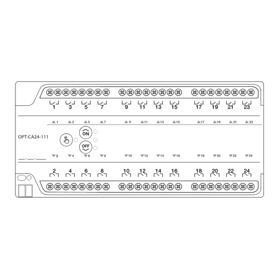
OPT-CA24-111
Kombine Aktuatör / Combo Actuator 24 kanal - channel
Function
Count of Function
Nr
1
3-speed Fan Coil Controller
2
2-Speed Fan Coil Controller
3
3-Point Valve Controller
4
Shutter Control
5
Switch/Valve Control
Kombine Aktuatör
Genel Özellikler
OPT-Caxx-111 farklı kullanım amaçlarının bir arada sunan KNX
uyumlu otomasyon cihazıdır. Şalter/Valf, Perde/Panjur, 3-Nok-
ta Motor ve Fan Coil kontrol işlemlerini tek bir cihaz üzerinden
yapılabilir. 4,8,12,16,20 ve 24 kontak çıkışı içeren modelleri bu-
lunmaktadır. Bağlantı tablosu üstte gösterilmiştir.
İzleme ve Manuel Kontrol: Cihaz üzerindeki tuşlar ile tüm kon-
trollere erişilebilir. Cihaz üzerindeki üçgen LED göstergeler ilgili
çıkışın kontak durumunu gösterir (bağlantının normalde açık
veya kapalı olma durumunu dikkate alınız). El sembolünün bu-
lunduğu tuş 6 , cihazın manuel kontrole geçmesine veya ma-
nuel kontrolden çıkması için kullanılır. Tuşa yarım saniye kadar
basıldığına cihaz manuel moda girer veya bu moddan çıkar. Ci-
haz manuel modda iken tuşun yanındaki LED yanar, ilk fonksiyon
çıkış(lar)ına ait üçgen durum LED(ler)i 5 yanıp söner. Fonksi-
yon kontrol tuşları 7 ilgili fonksiyonun çalışması kontrol edilir.
Ortadaki üç LED gösterge 8 , seçilen fonksiyonun durumunu
gösterir.
Bağlantılar: Cihazın besleme ve iletişim bağlantısı 4 numaralı
standart KNX klemensi ile yapılır. 3 cihazın adresleme tuşudur.
2 Cihazın adresleme göstergesidir. 1 cihaza atanmış olan adre-
sin yazım alanıdır.
Combo Actuator
General Specifications
OPT-Caxx-111 is a KNX compatible automation device that offers
different usage purposes together. Switch/Valve, Curtain/Blinds,
3-Point Motor and Fan Coil control operations can be done on a
single device. There are models with 4,8,12,16,20 and 24 contact
outputs. The connection table is shown at the top. Monitoring
and Manual Control:
All controls can be accessed with the keys on the device. Trian-
gular LED indicators on the device show the contact status of the
relevant output (consider whether the connection is normally
open or closed). The button 6 with the hand symbol allows the
device to switch to or exit from manual control. When the button
is pressed for half a second, the device enters or exits the manual
mode. When the device is in manual mode, the LED next to the
button lights up, the triangular status LED(s) 5 of the first func-
tion output(s) flash. Function control keys 7 The operation of
the relevant function is checked. The three central LED indicators
8 show the status of the selected function.
Connections: The supply and communication connection of
the device is made with the standard KNX terminal 4 . 3 is the
addressing key of the device. 2 It is the addressing indicator of
the device. 1 is the writing field of the address assigned to the
device.
Adres Yazma Alanı / Address Writing Area
Adresleme Göstergesi / Address Sign
Adresleme / Address Button
KNX Hat Bağlantısı / Data Bus
Çıkış Durum Göstergeleri / Output Status Indicators
Manual Mod Tuşu ve Göstergesi / Manual Mode Key and Indicator
Fonksiyon Kontrol Tuşları / Function Control Keys
Fonksiyon Durum Göstergesi / Function Status Indicator
Bağımsız Girişli Çıkış Terminalleri / Outputs with Individual Source
OPT-CA4-1111
OPT-CA8-1111
OPT-CA12-111
1
2
3
1
2
3
2
4
6
2
4
6
4
8
12
OPT-CA16-111
OPT-CA20-111
OPT-CA24-111
4
5
6
4
5
6
8
10
12
8
10
12
16
20
24
Teknik Özellikler
Besleme gerilimi
KNX 30 VDC
KNX akım tüketimi
Max. 10mA
KNX mod
S-Mod
Bağlantı
KNX Bağlantı
Koruma sınıfı
IP 20
Montaj
DIN Rayı
Çıkış sayısı
4, 8, 12, 16,20 veya 24
Çıkış anahtarlama akımları
16A 277 VAC
Çalışma
Sıcaklık aralıkları
Taşıma
Saklama
Ölçüler
(GxYxD)
4 çıkış
54 x 92 x 64 mm
8 çıkış
90 x 92 x 64 mm
12 çıkış
108 x 92 x 64 mm
16 çıkış
144x 92 x 64 mm
20 çıkış
198 x 92 x 64 mm
24 çıkış
198 x 92 x 64 mm
Muhafaza
ABS V0
Bağlantı Terminalleri
4 mm² çok damar, 6 mm² tek damar
Sertifika
CE
Technical Specifications
Supply Voltage
KNX 30 VDC
KNX Current Consumption
Max. 10mA
KNX mode
S-Mode
Connection
KNX Connection
Protection Class
IP 20
Mounting
DIN Rail
Number of Output
4, 8, 12, 16,20 or 24
Output switching currents
16A 277 VAC
Operation
Temperature Range
Transport
Storage
Dimensions
(WxHxD)
4 çıkış
54 x 92 x 64 mm
8 çıkış
90 x 92 x 64 mm
12 çıkış
108 x 92 x 64 mm
16 çıkış
144 x 92 x 64 mm
20 çıkış
198 x 92 x 64 mm
24 çıkış
198 x 92 x 64 mm
Housing
ABS V0
Connection Terminals
4 mm² çok damar, 6 mm² tek damar
Certificate
CE
Wiring
x1
x2
x3
x4
Low
Medium High
5
Low
High
3 4
5
Open Close
Open
Close
Up
Down
Up
Down
5
5
5
5
OPT-CA4-111
-10...70 °C
-25...70 °C
-25...100 °C
OPT-CA12-111
OPT-CA16-111
-10...70 °C
-25...70 °C
-25...100 °C
OPT-CA20-111
OPT-CA24-111
OPT-CA8-111
Advertisement

Related Manuals for Optimus OPT-CA4-111


Summary of Contents for Optimus OPT-CA4-111
- Page 1 OPT-CA4-111 Kombine Aktuatör / Combo Actuator 4 kanal - channel OPT-CA8-111 Kombine Aktuatör / Combo Actuator 8 kanal - channel OPT-CA12-111 Kombine Aktuatör / Combo Actuator 12 kanal - channel OPT-CA16-111 Kombine Aktuatör / Combo Actuator 16 kanal - channel OPT-CA20-111 Kombine Aktuatör / Combo Actuator 20 kanal - channel...
- Page 2 Bağlantı Şeması Örnekleri / Wiring Diagram Samples...
Need help?
Do you have a question about the OPT-CA4-111 and is the answer not in the manual?
Questions and answers