Advertisement
Quick Links
Advertisement

Related Manuals for Supermicro X14SAE


Summary of Contents for Supermicro X14SAE
- Page 1 X14SAE X14SAE-F USER'S MANUAL Revision 1.0 (MNL-2706)
- Page 2 The products sold by Supermicro are not intended for and will not be used in life support systems, medical equipment, nuclear facilities or systems, aircraft, aircraft devices, aircraft/emergency communication devices or other critical systems whose failure to perform be reasonably expected to result in significant injury or loss of life or catastrophic property damage.
- Page 3 Technical Support email addresses can be found at: "Contacting Supermicro" on page 11 If you have any feedback on Supermicro product manuals, contact our writing team at: Techwriterteam@supermicro.com This manual may be periodically updated without notice. Check the Supermicro website for...
- Page 4 X14SAE/X14SAE-F: Preface Conventions Used in the Manual Special attention should be given to the following symbols for proper installation and to prevent damage done to the components or injury to yourself. Warning! Indicates important information given to prevent equipment/property damage or personal injury.
- Page 5 X14SAE/X14SAE-F: Contents Contents Contacting Supermicro Chapter 1: Introduction 1.1 Quick Reference Checklist Motherboard Layout Quick Reference Table Motherboard Features Motherboard Block Diagram 1.2 Platform Overview 1.3 Special Features Recovery from AC Power Loss 1.4 System Health Monitoring Onboard Voltage Monitors...
- Page 6 Installing an M.2 Device with Heatsink (Optional) 2.7 Rear I/O Ports DisplayPort HDMI Port VGA Port (X14SAE-F) Unit Identifier Switch (X14SAE-F) LAN Ports and BMC LAN (X14SAE-F) USB Ports High Definition Audio (HD Audio) Ports 2.8 Front Control Panel Power Button Reset Button...
- Page 7 DOM Power Connector Fan Headers Front Panel Audio Header Internal Speaker/Buzzer M.2 M-Key PCIe 5.0/4.0 x4 Slots Power LED Header Power SMB (I²C) Header (X14SAE-F) Pump Power Header SATA 3.0 Ports SlimSAS 8i Connector Standby Power TPM/Port 80 Header USB Headers...
- Page 8 X14SAE/X14SAE-F: Contents Chapter 3: Troubleshooting 3.1 Troubleshooting Procedures Before Power On No Power No Video System Boot Failure Memory Errors Losing the System's Setup Configuration If the System Becomes Unstable If the RHEL 9.4 Installation Stops 3.2 Technical Support Procedures 3.3 Motherboard Battery...
- Page 9 Intel(R) Rapid Storage Technology Menu Driver Health Menu 4.4 Event Logs 4.5 BMC (X14SAE-F) System Event Log Menu BMC Network Configuration Menu 4.6 Security Secure Boot Menu Supermicro Security Erase Configuration Menu 4.7 Boot 4.8 Save & Exit 4.9 MEBx...
- Page 10 X14SAE/X14SAE-F: Contents Appendix A: BIOS Codes BIOS Error POST (Beep) Codes Additional BIOS POST Codes Appendix B: Software Microsoft Windows OS Installation Installing the OS Driver Installation SuperDoctor 5 BMC (X14SAE-F) BMC ADMIN User Password Appendix C: Standardized Warning Statements...
- Page 11 X14SAE/X14SAE-F: Contacting Supermicro Contacting Supermicro Headquarters Address: Super Micro Computer, Inc. 980 Rock Ave. San Jose, CA 95131 U.S.A. Tel: +1 (408) 503-8000 Fax: +1 (408) 503-8008 Email: Marketing@supermicro.com (General Information) Sales-USA@supermicro.com (Sales Inquiries) Government_Sales-USA@supermicro.com (Gov. Sales Inquiries) Support@supermicro.com (Technical Support) RMA@Supermicro.com...
- Page 12 X14SAE/X14SAE-F: Introduction Chapter 1: Introduction Congratulations on purchasing your computer motherboard from an industry leader. Supermicro motherboards are designed to provide you with the highest standards in quality and performance. 1.1 Quick Reference Checklist Motherboard Layout Quick Reference Table Motherboard Features Motherboard Block Diagram 1.2 Platform Overview...
- Page 13 For details on the X14SAE/X14SAE-F motherboard layout, features, and other quick reference information, refer to the content below. Checklist In addition to the X14SAE/X14SAE-F motherboard, several important parts that are included in your shipment are listed below. If anything listed is damaged or missing, contact your retailer. Main Parts List...
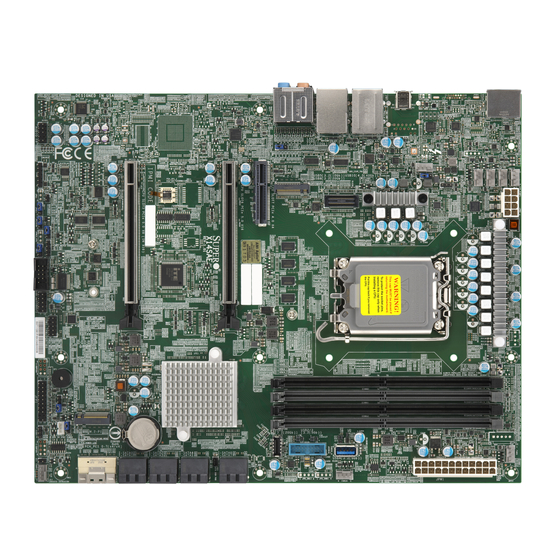
- Page 14 X14SAE/X14SAE-F: Introduction Motherboard Layout Figure 1-1. X14SAE Motherboard Image...
- Page 15 X14SAE/X14SAE-F: Introduction Figure 1-2. X14SAE-F Motherboard Image...
- Page 16 X14SAE/X14SAE-F: Introduction Figure 1-3. X14SAE Motherboard Layout...
- Page 17 X14SAE/X14SAE-F: Introduction Figure 1-4. X14SAE-F Motherboard Layout Notes: "Component Installation" on page 31 for detailed information on jumpers, connectors, and LED indicators. "■" indicates the location of pin 1. Components not documented are for internal testing-purposes only. Use only the correct type of onboard CMOS battery as specified by the manufacturer.
- Page 18 Pins 1–2 (Enabled) Pins 1–2: Slot3 1x8 (Default) JPCIESW CPU PCIe SLOT3 1x8/2x4 Pins 2–3: Slot3 2x4 JPG1 VGA Enable/Disable (X14SAE-F only) Pins 1–2 (Enabled) JPL1, JPL2 LAN1/LAN2 Enable/Disable Pins 1–2 (Enabled) JPME2 ME Manufacturing Mode Pins 1–2 (Normal) JPT1 Onboard TPM 2.0 Enable/Disable...
- Page 19 * The default setting is for a headphone/microphone combo jack. If not using a AUDIO FP chassis with the headphone/microphone combo jack, configure Frontside Audio Mode in the BIOS Setup utility. BMC_LAN Dedicated BMC LAN Port (X14SAE-F only) Onboard Battery COM1 COM Header DP_HDMI DP: Rear DisplayPort 2.1.
- Page 20 Front Accessible USB 3.2 Gen 2x2 Header (20 Gb, Type-C) USB10 Rear Thunderbolt 4 (TBT 4) Port (40 Gb, Type-C) VGA Port supported by BMC (X14SAE-F only) Motherboard Features Motherboard Features Processor Supports a single Intel® Core™ Ultra 9/7/5 series processor (in LGA 1851 Socket) and a thermal design power (TDP) of up to 125W Note: The processor TDP is subject to chassis and heatsink cooling restrictions.
- Page 21 SLOT6 will function at PCIe 1x8 when SLOT3 is populated or when SLOT3 is configured to 2x4 bifurcation mode. Network Controller Intel Ethernet i219-LM (1 GbE LAN)(for AMT/vPro) Intel Ethernet i226-LM (2.5 GbE LAN port,X14SAE) Intel Ethernet i225-LM (2.5 GbE LAN port, X14SAE-F) Realtek RTL8211F (dedicated BMC LAN port, X14SAE-F )
- Page 22 One SlimSAS 8i connector supporting two U.2 connections One DisplayPort 2.1 connection on the rear I/O One HDMI 2.1 connection on the rear I/O One VGA connection on the rear I/O (X14SAE-F) Peripheral Devices One Thunderbolt 4 port on the rear I/O (40 Gb, Type-C, USB10) Three USB 3.2 Gen 2x1 ports on the rear I/O (10 Gb, Type-A, USB5–USB7)
- Page 23 Five CPU switch phase voltage regulators CPU thermal trip support Platform Environment Control Interface (PECI)/TSI Fan Control Triple cooling zones Multi-speed fan control via Embedded Controller (X14SAE) or BMC (X14SAE-F) Seven 4-pin fan headers System Management SuperServer Automation Assistant (SAA) Trusted Platform Module (TPM) support SuperDoctor®...
- Page 24 X14SAE/X14SAE-F: Introduction Motherboard Block Diagram Figure 1-5. Motherboard Block Diagram...
- Page 25 Built upon the functionality and capability of the Intel® Core™ Ultra 9/7/5 series (in LGA 1851 Socket) and the Intel 800 Series chipset, the X14SAE/X14SAE- F motherboard provides system performance, power efficiency, and feature sets to address the needs of next- generation computer users.
- Page 26 X14SAE/X14SAE-F: Introduction 1.3 Special Features Recovery from AC Power Loss The Basic I/O System (BIOS) provides a setting that determines how the system will respond when AC power is lost and then restored to the system. You can choose for the system to remain powered off (in which case you must press the power switch to turn it back on), or for it to automatically return to the power-on state.
- Page 27 PC health monitoring in the BIOS can check the RPM status of the cooling fans. The onboard CPU and chassis fans are controlled by Thermal Management via Embedded Controller (EC) for X14SAE or BMC for X14SAE-F. Environmental Temperature Control The thermal control sensor monitors the CPU temperature in real time and will turn on the thermal control fan whenever the CPU temperature exceeds a user-defined threshold.
- Page 28 Windows operating systems. For detailed information regarding OS support, please refer to the Supermicro website. Slow Blinking LED for Suspend-state Indicator When the CPU goes into a suspend state, the chassis power LED will start to blink to indicate that the CPU is in suspend mode.
- Page 29 X14SAE/X14SAE-F: Introduction 1.6 Serial Header The X14SAE/X14SAE- F motherboard supports one serial communication connection. The COM header can be used for input/output. The UART supports speeds with a baud rate of 115.2 Kbps, 57.6 Kbps, 38.4 Kbps, 19.2 Kbps, and 9.6 Kbps.
- Page 30 X14SAE/X14SAE-F: Introduction 1.7 Embedded Controller The Embedded Controller supports one high-speed, 16550 compatible serial communication port (UART). Each UART includes a 16-byte send/receive FIFO, a programmable baud rate generator, complete modem control capability and a processor interrupt system. The UART supports speeds with a baud rate of 115.2 Kbps, 57.6 Kbps, 38.4 Kbps, 19.2 Kbps, and 9.6...
- Page 31 Component Installation This chapter provides instructions on installing and replacing main system components for the X14SAE/X14SAE-F motherboard. To prevent compatibility issues, only use components that match the specifications and/or part numbers given. Installation or replacement of most components require that power first be removed from the system.
- Page 32 X14SAE/X14SAE-F: Component Installation HDMI Port VGA Port (X14SAE-F) Unit Identifier Switch (X14SAE-F) LAN Ports and BMC LAN (X14SAE-F) USB Ports High Definition Audio (HD Audio) Ports 2.8 Front Control Panel Power Button Reset Button Power Fail LED (X14SAE-F) Overheat (OH)/Fan Fail LED...
- Page 33 X14SAE/X14SAE-F: Component Installation 2.1 Static-Sensitive Devices Electrostatic Discharge (ESD) can damage electronic components. To avoid damaging your motherboard, it is important to handle it very carefully. The following measures are generally sufficient to protect your equipment from ESD. Precautions Use a grounded wrist strap designed to prevent static discharge.
- Page 34 X14SAE/X14SAE-F: Component Installation 2.2 Motherboard Installation All motherboards have standard mounting holes to fit different types of chassis. Make sure that the locations of all the mounting holes for both the motherboard and the chassis match. Although a chassis may have both plastic and metal mounting fasteners, metal ones are highly recommended because they ground the motherboard to the chassis.
- Page 35 X14SAE/X14SAE-F: Component Installation Note: Images displayed are for illustration purposes only. The components installed in your system may or may not look exactly the same as the graphics shown in the manual. 2. Locate the mounting holes on the motherboard. See Motherboard Installation for the location.
- Page 36 Install the processor in the socket and the motherboard into the chassis before installing the heatsink. When buying a processor separately, use only a Supermicro certified heatsink. Refer to the Supermicro website for the most recent processor support. When installing the heatsink, ensure a torque driver set to the correct force is used for each screw.
- Page 37 X14SAE/X14SAE-F: Component Installation 1. Remove the plastic protective cover from the load plate. Figure 2-5. Remove the Protective Cover 2. Gently push the load lever down and away from the lever lock. Then lift it up completely. Figure 2-6. Release and Lift Up the Lever...
- Page 38 X14SAE/X14SAE-F: Component Installation 3. Lift the load plate to open it completely. Figure 2-7. Open the load plate 4. Carefully hold the processor by its edges. Align the small triangle marker and notches on the processor with the corresponding triangle marker and notches on the processor load bracket.
- Page 39 X14SAE/X14SAE-F: Component Installation 6. With the processor inside the socket, inspect all the corners to make sure it is properly installed. 7. Close the load plate with the processor inside the socket. Gently push the load lever down until it locks under the lever lock.
- Page 40 X14SAE/X14SAE-F: Component Installation 1. Loosen four screws to release the backplate. Note that one screw is not shown in the illustration below. Figure 2-10. Release the Backplate from the Heatsink 2. If there is a thin layer of protective film on the backplate, remove it.
- Page 41 X14SAE/X14SAE-F: Component Installation 3. Attach the backplate into the mounting holes around the processor socket on the bottom side of the motherboard. Figure 2-12. Attach the Backplate to the Bottom Side of the Motherboard 4. Apply the proper amount of thermal grease on the processor.
- Page 42 X14SAE/X14SAE-F: Component Installation 6. Tighten the screws. Figure 2-14. Tighten the Heatsink Screws Removing the Processor Heatsink Important: We do not recommend that the processor or heatsink be removed. However, if you do need to remove the heatsink, follow the instructions below to remove the heatsink and prevent damage done to the processor or other components.
- Page 43 X14SAE/X14SAE-F: Component Installation 3. Gently wiggle the heatsink to loosen it. Do not use excessive force when wiggling the heatsink. Figure 2-15. Loosen the Heatsink Screws 4. Once the heatsink is loosened, remove it from the motherboard.
- Page 44 Note: Check the Supermicro website for recommended memory modules. Memory Support The X14SAE/X14SAE- F motherboard supports up to 192 GB of Unbuffered (UDIMM) ECC/Non-ECC DDR5 memory with speeds of up to 5600 MT/s (1DPC), 4800 MT/s (2DPC, 1R DIMM ), and 4400 MT/s (2DPC, 2R DIMM) in four 288-pin memory slots.
- Page 45 X14SAE/X14SAE-F: Component Installation General Guidelines for Optimizing Memory Performance It is recommended to use DDR5 memory of the same type, size, and speed. Mixed DIMM speeds can be installed. However, all DIMMs will run at the speed of the slowest DIMM.
- Page 46 X14SAE/X14SAE-F: Component Installation 3. Align the key of the DIMM with the receptive point on the memory slot. Figure 2-17. Align the DIMM Slot with the Receptive Point 4. Align the notches on both ends of the module against the receptive points on the ends of the slot.
- Page 47 X14SAE/X14SAE-F: Component Installation Figure 2-19. Press Both Ends For a detailed diagram of the X14SAE/X14SAE-F motherboard, see the layout under "Quick Reference" on page DIMM Removal Important: Do not use excessive force when pressing the release tabs on the ends of the DIMM socket to avoid causing any damage to the memory module or the DIMM socket.
- Page 48 X14SAE/X14SAE-F: Component Installation For a detailed diagram of the X14SAE/X14SAE-F motherboard, see the layout under "Quick Reference" on page...
- Page 49 X14SAE/X14SAE-F: Component Installation 2.5 Battery Removal and Installation Battery Removal To remove the onboard battery, follow the steps below: 1. Power off your system and unplug your power cable. 2. Locate the onboard battery as shown below. 3. Using a tool such as a pen or a small screwdriver, push the battery lock outwards to unlock it.
- Page 50 X14SAE/X14SAE-F: Component Installation 2.6 M.2 Device Installation This motherboard has one PCIe 5.0 M.2 M- key slot (M.2- C1) that supports the M.2 2280 modules and one PCIe 4.0 M.2 M-key slot (M.2-P1) that supports the 2280/22110 modules. Two standoffs are pre-installed in the position of 2280 mounting hole (M.2-C1) and 22110 mounting hole (M.2-P1).
- Page 51 X14SAE/X14SAE-F: Component Installation 2. If the soon-to-be used mounting hole doesn't have a standoff, move the pre-installed one to that mounting hole. Figure 2-21. Change the Standoff Position as Needed 3. Carefully insert the M.2 device into the M.2 slot at a 30-degree angle and lower the semi- circle notched end onto the standoff.
- Page 52 It is strongly recommended that you install an M.2 heatsink provided by the M.2 device supplier. If you are using a Supermicro M.2 heatsink, follow the steps below: Note: Images displayed are for illustration only. Your M.2 heatsink may not look exactly the same as the graphics shown in the manual.
- Page 53 X14SAE/X14SAE-F: Component Installation 3. Tighten the screws to secure the M.2 heatsink assembly. Figure 2-26. Secure the M.2 Heatsink Assembly 4. Locate the pre-installed standoff and screw . Remove the screw and set it aside. Figure 2-27. Remove the Screw on the Pre-installed Standoff...
- Page 54 X14SAE/X14SAE-F: Component Installation 5. If the soon-to-be used mounting hole doesn't have a standoff, move the pre-installed one to that mounting hole. Figure 2-28. Change the Standoff Position as Needed 6. Carefully insert the M.2 assembly into the M.2 slot at a 30-degree angle and lower the assembly onto the standoff.
- Page 55 One High- Definition Multimedia Interface (HDMI) 2.1 port is located on the rear I/O of the X14SAE/X14SAE-F motherboard. This port is used to display both high definition video and digital sound through an HDMI display, using a single HDMI cable (not included).
- Page 56 Unit Identifier Switch (X14SAE-F) A Unit Identifier (UID) switch is located on the rear I/O of the X14SAE-F motherboard, and a UID LED is located near the UID switch. When you press the UID switch on and off, it will turn the UID LED on and off to identify a system unit that may need services.
- Page 57 X14SAE/X14SAE-F: Component Installation High Definition Audio (HD Audio) Ports This X14SAE/X14SAE-F features a 7.1+2 Channel High Definition Audio (HDA) codec that provides 10 DAC channels. The HD Audio connections simultaneously supports multiple- streaming 7.1 sound playback with 2 channels of independent stereo output through the front panel stereo out for front, rear, center and subwoofer speakers.
- Page 58 These connectors are designed specifically for use with Supermicro chassis. See the figure below for the descriptions of the front control panel buttons and LED indicators.
- Page 59 Pin# Definition Reset Power Fail LED (X14SAE-F) The Power Fail LED connection is located on pins 5 and 6 of JFP1 on the X14SAE/X14SAE-F motherboard. For a detailed diagram of the X14SAE/X14SAE-F motherboard, see the layout under "Quick Reference" on page...
- Page 60 The Network Interface Controller (NIC) LED connection for LAN port 1 is located on pins 11 and 12 of JFP1 on the X14SAE/X14SAE-F motherboard, and LAN port 2 is on pins 9 and 10. Attach the NIC LED cables here to display network activity.
- Page 61 UID Switch/HDD LED The UID Switch (X14SAE-F only)/HDD LED connection is located on pins 13 and 14 of JFP1 on the motherboard. Attach a cable to pin 13 to use the UID switch. Attach a cable to pin 14 to show storage drive activity status.
- Page 62 X14SAE/X14SAE-F: Component Installation NMI Button Pin Definitions (JFP1) Pin# Definition Control...
- Page 63 Refer to the following sections for information about connections, jumpers, and LEDs for the X14SAE/X14SAE-F motherboard. Power Connections For information about the power connections of the X14SAE/X14SAE-F motherboard, refer to the following content. Important: To provide adequate power supply to the motherboard, be sure to connect the 24-pin ATX PWR and the 8-pin PWR connections to the power supply.
- Page 64 +5 V +12 V +3.3 V Headers and Connections For information about the headers of the X14SAE/X14SAE- F motherboard, refer to the following content. Chassis Intrusion A Chassis Intrusion header is located at JL1 on the X14SAE/X14SAE-F motherboard. Attach the appropriate cable from the chassis to inform you when the chassis is opened.
- Page 65 X14SAE/X14SAE-F: Component Installation COM Header There is one COM header at COM1 on the X14SAE/X14SAE-F motherboard. Use a cable with the COM header to access the COM1 COM port. COM ports provide serial communication support. For a detailed diagram of the X14SAE/X14SAE-F motherboard, see the layout under "Quick...
- Page 66 PWM Control Front Panel Audio Header A 10-pin audio header located at AUDIO_FP/AUDIO FP is supported on the X14SAE/X14SAE- F motherboard. This header allows you to connect the motherboard to the audio port on the front panel. If needed, connect an audio cable (not supplied) to the audio header to use this feature.
- Page 67 Beep In Neg (-) Alarm Speaker M.2 M-Key PCIe 5.0/4.0 x4 Slots Two M.2 M- key slots are located at M.2- C1 and M.2- P1 on the X14SAE/X14SAE- F motherboard. Refer to the table below for more information. Slots Signals...
- Page 68 PMBUS_Alert +3.3 V Pump Power Header The X14SAE/X14SAE-F motherboard has one +12 V header for optional CPU liquid cooling systems. When using a liquid cooling system, attach the pump power cable to the 12V_PUMP1 header. For a detailed diagram of the X14SAE/X14SAE-F motherboard, see the layout under "Quick...
- Page 69 +5 V Standby TPM/Port 80 Header The JTPM1 header on the X14SAE/X14SAE- F motherboard is used to connect a Trusted Platform Module (TPM)/Port 80, which is available from Supermicro (optional). A TPM/Port 80 connector is a security device that supports encryption and authentication in hard drives. It allows the motherboard to deny access if the TPM associated with the hard drive is not installed in the system.
- Page 70 There is one USB 2.0 header (USB0/1) and one USB 3.2 Gen 1x1 header (USB2/3) on the X14SAE/X14SAE-F motherboard, each supporting two USB connections. There is also one USB 3.2 Gen 1x1 header (USB4, vertical), and one USB 3.2 Gen 2x2 header (USB9) located on the motherboard.
- Page 71 Note: On two-pin jumpers, "Closed" means the jumper is on and "Open" means the jumper is off the pins. CMOS Clear JBT1 on the X14SAE/X14SAE-F motherboard is used to clear CMOS, which will also clear any passwords. Instead of pins, this jumper consists of contact pads to prevent accidentally clearing the contents of CMOS.
- Page 72 For a detailed diagram of the X14SAE/X14SAE-F motherboard, see the layout under "Quick Reference" on page External Speaker/Buzzer Jumper Settings Pin# Definition Pins 1–4 External Speaker Pins 3–4 Buzzer (Default) HD Audio Enable/Disable Use JPAC1 to enable or disable HD Audio on the X14SAE/X14SAE- F motherboard. The default setting is Enabled.
- Page 73 Jumper Settings Jumper Setting Definition Pins 1–2 Enabled (Default) Pins 2–3 Disabled LAN Enable/Disable Use JPL1/JPL2 to enable or disable LAN1/LAN2 on the X14SAE/X14SAE- F. The default setting is Enabled. LAN Enable/Disable Jumper Settings Jumper Setting Definition Pins 1–2 Enabled (Default) Pins 2–3...
- Page 74 Disabled VGA Enable/Disable (X14SAE-F) Jumper JPG1 allows you to enable the onboard VGA connector on the X14SAE- F motherboard. The default setting is pins 1–2 to enable the connection. For a detailed diagram of the X14SAE/X14SAE-F motherboard, see the layout under "Quick...
- Page 75 System CATERR LAN1/LAN2 LEDs Each of the LAN1 and LAN2 ports of the rear I/O of the X14SAE/X14SAE-F motherboard features two LEDs. The LED on the right indicates activity, and the LED on the left indicates the speed of the connection.
- Page 76 S3, suspend to RAM Standby Power / BMC Heartbeat LED For X14SAE, the LEDBMC works as a standby power LED. When the LED is solid green, the standby power is on. For X14SAE-F, the LEDBMC works as a BMC Heartbeat LED. When this LED is blinking, the BMC is functioning normally.
- Page 77 X14SAE/X14SAE-F: Troubleshooting Chapter 3: Troubleshooting The following content contains information on common issues and how to resolve them. 3.1 Troubleshooting Procedures Before Power On No Power No Video System Boot Failure Memory Errors Losing the System's Setup Configuration If the System Becomes Unstable If the RHEL 9.4 Installation Stops...
- Page 78 X14SAE/X14SAE-F: Troubleshooting 3.1 Troubleshooting Procedures Use the following procedures to troubleshoot your system. If you have followed all of the procedures below and still need assistance, refer to the Technical Support Procedures Returning Merchandise for Service section(s) in this chapter. Always disconnect the AC power cord before adding, changing or installing any non hot- swap hardware components.
- Page 79 X14SAE/X14SAE-F: Troubleshooting 1. Check the screen for an error message. 2. Clear the CMOS settings by unplugging the power cord and contacting both pads on the CMOS clear jumper. Restart the system. Refer to CMOS Clear. 3. Remove all components from the motherboard and turn on the system with only one DIMM installed.
- Page 80 X14SAE/X14SAE-F: Troubleshooting 2. Memory support: Make sure that the memory modules are supported. Refer to the product page on our website at https://www.supermicro.com. Test the modules using memtest86 or a similar utility. Note: Click on the "Tested Memory List" link on the motherboard's product page to see a list of supported memory.
- Page 81 X14SAE/X14SAE-F: Troubleshooting If the RHEL 9.4 Installation Stops If the RHEL 9.4 installation process stops at "Started GNOME Display Manager," you can resolve this issue by following the workaround recommended by Red Hat: 1. Switch to text mode during the installation.
- Page 82 Before contacting Technical Support, take the following steps. Also, note that as a motherboard manufacturer, Supermicro also sells motherboards through its channels, so it is best to first check with your distributor or reseller for troubleshooting services. They should know of any possible problems with the specific system configuration that was sold to you.
- Page 83 X14SAE/X14SAE-F: Troubleshooting 3.3 Motherboard Battery For information on removing, disposing of, and replacing the motherboard battery of your system, refer to "Battery Removal and Installation" on page...
- Page 84 X14SAE/X14SAE-F: Troubleshooting 3.4 Where to Get Replacement Components If you need replacement parts for your X14SAE/X14SAE-F motherboard, to ensure the highest level of professional service and technical support, purchase exclusively from our Supermicro Authorized Distributors/System Integrators/Resellers. A list can be found on the Supermicro website: https://www.supermicro.com...
- Page 85 For faster service, RMA authorizations can be requested online at the following page: https://www.supermicro.com/RmaForm Whenever possible, repack the motherboard in the original Supermicro carton, using the original packaging material. If these are no longer available, be sure to pack the motherboard securely, using packaging material to surround the motherboard so that it does not shift within the carton and become damaged during shipping.
- Page 86 X14SAE/X14SAE-F: Troubleshooting 3.6 Feedback Supermicro values your feedback as we strive to improve our customer experience in all facets of our business. Email us at Techwriterteam@supermicro.com to provide feedback on our manuals.
- Page 87 X14SAE/X14SAE-F: UEFI BIOS Chapter 4: UEFI BIOS The following content contains information on BIOS configuration with the X14SAE/X14SAE-F motherboard. 4.1 Introduction 4.2 Main Setup 4.3 Advanced Setup Configurations 4.4 Event Logs 4.5 BMC (X14SAE-F) 4.6 Security 4.7 Boot 4.8 Save & Exit...
- Page 88 X14SAE/X14SAE-F: UEFI BIOS 4.1 Introduction This chapter describes the AMIBIOS™ Setup utility for the motherboard. The BIOS is stored on a chip and can be easily upgraded using the UEFI script (flash.nsh), the BMC WebUI, or the SuperServer Automation Assistant (SAA) utility.
- Page 89 X14SAE/X14SAE-F: UEFI BIOS selected in the left frame, it is highlighted in white. Often a text message will accompany it. (Note that BIOS has default text messages built in. We retain the option to include, omit, or change any of these text messages.) Settings printed in Bold are the default values.
- Page 90 X14SAE/X14SAE-F: UEFI BIOS 4.2 Main Setup The Main setup screen appears when the AMI BIOS Setup utility is first entered. To return to the Main setup screen, select the Main tab at the top of the screen. The Main BIOS setup screen is shown below.
- Page 91 X14SAE/X14SAE-F: UEFI BIOS Build Date This feature displays the date when the version of the BIOS ROM used in the system was built. EC Version This feature displays the version of the Embedded Controller (EC) used in the system. Memory Information Total Memory This feature displays the total size of memory available in the system.
- Page 92 X14SAE/X14SAE-F: UEFI BIOS 4.3 Advanced Setup Configurations Use the arrow keys to select the Advanced submenu and press <Enter> to access the submenu items. Important: Use caution when changing the Advanced settings. An incorrect value, an improper DRAM frequency, or a wrong BIOS timing setting may cause the system to malfunction.
- Page 93 X14SAE/X14SAE-F: UEFI BIOS WHEA Support Select Enabled to support the Windows Hardware Error Architecture (WHEA) platform and provide a common infrastructure for the system to handle hardware errors within the Windows OS environment to reduce system crashes and to enhance system recovery and health monitoring.
- Page 94 X14SAE/X14SAE-F: UEFI BIOS Wait For "F1" If Error Select Enabled to force the system to wait until the <F1> key is pressed if an error occurs. The options are Disabled and Enabled. Re-try Boot If this feature is set to Enabled, the system BIOS will automatically reboot the system from an Extensible Firmware Interface (EFI) boot device after an initial boot failure.
- Page 95 X14SAE/X14SAE-F: UEFI BIOS CPU Signature Microcode Patch Max CPU Speed Min CPU Speed CPU Speed Number of Performance-core(s) Number of Efficient-core(s) Hyper Threading Technology SMX/TXT 64-bit EIST Technology CPU C3–C10 State Performance L1 Data Cache Performance L1 Instruction Cache Performance L2 Cache...
- Page 96 X14SAE/X14SAE-F: UEFI BIOS Active Efficient-cores This feature determines how many efficient cores will be activated for each processor package. When all is selected, all cores in the processor will be activated. The options are All, 15, 14, 13, 12, 11, 10, 9, 8, 7, 6, ,5, 4, 3, 2, and 1.
- Page 97 X14SAE/X14SAE-F: UEFI BIOS Power Limit 2 Use this feature to configure the value for Power Limit 2. The value is in milliwatts and the step size is 125 mW. Use the number keys on your keyboard to enter the value. Enter 0 to use the manufacture default setting.
- Page 98 X14SAE/X14SAE-F: UEFI BIOS Performance Mode Select Enabled for optimal performance, which may increase the risk of CPU overheating. Select Disabled for thermal safety, which may limit CPU performance. The options are Disabled and Enabled. Chipset Configuration Menu ►Chipset Configuration Important: Setting the wrong values in this section may cause the system to malfunction.
- Page 99 X14SAE/X14SAE-F: UEFI BIOS DIMMA1 DIMMA2 DIMMB1 DIMMB2 Maximum Memory Frequency Use this feature to set the maximum memory frequency for onboard memory modules. The options are Auto, 1600, 2400, 3200, 3600, 4000, 4200, 4400, 4600, 4800, 5000, 5200, 5400, 5600, 5800, 6000, 6200, and 6400.
- Page 100 X14SAE/X14SAE-F: UEFI BIOS Graphics Configuration Menu ►Graphics Configuration This submenu allows you to configure the graphics configuration settings. Graphics Configuration IGFX GOP Version Skip Scanning of External Gfx Card If this feature is enabled, the system will not scan for an external graphics card on PEG and PCIe slots.
- Page 101 X14SAE/X14SAE-F: UEFI BIOS PEG Port Configuration ►PEG Port Configuration CPU SLOT6 PCIe 5.0 x16 CPU SLOT3 PCIe 5.0 x8 (IN X16) CPU SLOT3 PCIe 5.0 x8 (IN X16) Enable Root Port Use this feature to enable or disable the PCIe Graphics (PEG) device in the specified port . The options are Disabled and Enabled.
- Page 102 X14SAE/X14SAE-F: UEFI BIOS Maximum GT Frequency Use this feature to define the Maximum GT frequency. Choose between 1650 MHz (RPN) and 6000 MHz (RP0). Any value beyond this range will be clipped to its min/max supported by the CPU. The options are Default Max Frequency, 100Mhz, 150Mhz, 200Mhz, 250Mhz, 300Mhz, 350Mhz, 400Mhz, 450Mhz, 500Mhz, 550Mhz, 600Mhz, 650Mhz, 700Mhz, 750Mhz, 800Mhz, 850Mhz, 900Mhz, 950Mhz, 100Mhz, 1050Mhz, 1100Mhz, 1150Mhz, and 1200Mhz.
- Page 103 HTTPS Boot Checks Hostname Important: Disabling "HTTPS Boot Checks Hostname" is a violation of RFC 6125 and may expose you to Man-in-the-Middle Attacks. Supermicro is not responsible for any and all security risks incurred by you disabling this feature. Enable this feature for HTTPS boot to check the hostname of the TLS certificates to see if it matches the host name provided by the remote server.
- Page 104 X14SAE/X14SAE-F: UEFI BIOS Boot URI Enter a Boot Uniform Research Identifier (URI) with 128 characters or shorter. This Boot URI determines how IPv4 Boot Option and IPv6 Boot Option will be created. This feature is only supported on Dual or EFI Boot Mode.
- Page 105 X14SAE/X14SAE-F: UEFI BIOS Network Stack Configuration Menu ►Network Stack Configuration Network Stack Select Enabled to enable Preboot Execution Environment (PXE) or Unified Extensible Firmware Interface (UEFI) for network stack support. The options are Disabled and Enabled. IPv4 PXE Support (Available when "Network Stack" is set to Enabled) Select Enabled to enable IPv4 PXE boot support.
- Page 106 X14SAE/X14SAE-F: UEFI BIOS Enable DHCP (Available when "Configured" is set to Enabled) Select Enabled to support Dynamic Host Configuration Protocol (DHCP), which allows the BIOS to search for a DHCP server attached to the network and request the next available IP address for this computer.
- Page 107 X14SAE/X14SAE-F: UEFI BIOS Interface ID Use this feature to change/enter the 64-bit alternative interface ID for the device. The string format is colon separated. The default setting is the MAC address above. DAD Transmit Count Use this feature to set the number of consecutive neighbor solicitation messages have been sent while performing duplicate address detection on a tentative address.
- Page 108 X14SAE/X14SAE-F: UEFI BIOS Local IP Address (Available when "Configured" is set to Enabled and "Enabled DHCP" is set to Disabled) Use this feature to enter an IP address for the local machine. Local NetMask (Available when "Configured" is set to Enabled and "Enabled DHCP" is set to Disabled) Use this feature to set the netmask for the local machine.
- Page 109 X14SAE/X14SAE-F: UEFI BIOS DAD Transmit Count Use this feature to set the number of consecutive neighbor solicitation messages have been sent while performing duplicate address detection on a tentative address. The default setting is 1. Policy Use this feature to select how the policy is to be configured. The options are automatic and manual.
- Page 110 X14SAE/X14SAE-F: UEFI BIOS AMT Configuration USB Provisioning of AMT Use this feature to enable or disable USB provisioning. The options are Disabled and Enabled. MAC Pass Through Use this feature to enable or disable the MAC Pass Through function. The options are Disabled and Enabled.
- Page 111 X14SAE/X14SAE-F: UEFI BIOS One Click Recovery (OCR) Configuration OCR Https Boot Use this feature to enable or disable One Click Recovery Https Boot. One Click Recovery is a recovery process that lets you restore your computer to its last known good state with a single command.
- Page 112 Disabled and Enabled. Compatibility device Support Select Enabled if Supermicro add- on card AOC- SLG3- 2M2 is installed in SLOT3 of the motherboard. The options are Disabled and Enabled. Note: This feature is for SLOT3 only, and do not select Enabled if AOC-SLG3-2M2 is not installed.
- Page 113 X14SAE/X14SAE-F: UEFI BIOS SATA and RST Configuration SATA And RST Configuration SATA Controller(s) Use this feature to enable or disable the onboard SATA controller supported by the Intel PCH chip. The options are Enabled and Disabled. Support Aggressive Link Power Management When this feature is set to Enabled, the SATA AHCI controller manages the power usage of the SATA link.
- Page 114 X14SAE/X14SAE-F: UEFI BIOS Map PCH SATA Controller under VMD (Available when Enable VMD Controller is set to "Enabled") Use this feature to map or unmap the selected root port to VMD. The options are Disabled and Enabled. Serial Port Console Redirection Menu ►Serial Port Console Redirection...
- Page 115 X14SAE/X14SAE-F: UEFI BIOS Select ANSI to use the Extended ASCII Character Set. Select VT- UTF8 to use UTF8 encoding to map Unicode characters into one or more bytes. The options are VT100, VT100+, VT-UTF8, and ANSI. Bits Per Second Use this feature to set the transmission speed for a serial port used in Console Redirection.
- Page 116 X14SAE/X14SAE-F: UEFI BIOS Resolution 100x31 Select Enabled for extended- terminal resolution support. The options are Disabled and Enabled. Putty KeyPad This feature selects Function Keys and KeyPad settings for Putty, which is a terminal emulator designed for the Windows OS. The options are VT100, LINUX, XTERMR6, SCO, ESCN, and VT400.
- Page 117 X14SAE/X14SAE-F: UEFI BIOS Bits Per Second EMS This feature sets the transmission speed for a serial port used in Console Redirection. Make sure that the same speed is used in the host computer and the client computer. A lower transmission speed may be required for long and busy lines. The options are 9600, 19200, 57600, and 115200 (bits per second).
- Page 118 X14SAE/X14SAE-F: UEFI BIOS Active PCR banks Available PCR banks * The following features are available when the TPM 2.0 (either onboard or external) is detected by the BIOS. SHA256 PCR Bank (Available when "Security Device Support" is set to Enabled) Select Enabled to enable SHA256 PCR Bank support to enhance system integrity and data security.
- Page 119 X14SAE/X14SAE-F: UEFI BIOS can be encrypted and certified with a certificate created by using TPM2_ActivateCredential, which allows the user to independently enable "flag, policy, and authorization values" without involving other hierarchies. A user with privacy concerns can disable the endorsement hierarchy while still using the storage hierarchy for TPM applications, permitting the platform software to use the TPM.
- Page 120 X14SAE/X14SAE-F: UEFI BIOS Intel(R) Ethernet Connection (19) I219-V - (MAC address) Menu ►Intel(R) Ethernet Connection (19) I219-V - (MAC address) Autonegotiation Timeout This features controls how long the UEFI PXE driver should wait for link. The default is 8. PORT CONFIGURATION INFORMATION...
- Page 121 X14SAE/X14SAE-F: UEFI BIOS ►Enroll Certification This feature allows you to enroll the certificate in the system. ►Enroll Certification Using File This feature allows you to enroll the security certificate in the system by using a file. Certification GUID Press <Enter> and input the certification Global Unique Identifier (GUID).
- Page 122 X14SAE/X14SAE-F: UEFI BIOS RAID Level Select the desired RAID level for the RAID volume. The options are RAID0 (Stripe), RAID1 (Mirror), RAID5 (Parity), and RAID10 (RAID0+1). Available RAID levels depend on the number of disks connected to the system. Select Disks To select a desired RAID disk, select X from the drop-down list.
- Page 123 X14SAE/X14SAE-F: UEFI BIOS Size Status Bootable RAID Member Disks This feature displays the RAID member disks. Reset to non-RAID This feature allows you to reset a RAID member disks to non-RAID disk. When asked to remove the RAID structure on the disk, select Yes to reset the disk.
- Page 124 X14SAE/X14SAE-F: UEFI BIOS 4.4 Event Logs Use this menu to configure Event Logs settings. Note: After making any changes in this section, please be sure to reboot the system for the changes to take effect. Figure 4-3. Event Logs Screen ►Change SMBIOS Event Log Settings...
- Page 125 X14SAE/X14SAE-F: UEFI BIOS Erasing Settings Erase Event Log (Available when "SMBIOS Event Log" is set to Enabled) Select No to keep the event log without erasing it upon next system bootup. Select (Yes, Next reset) to erase the event log upon next system reboot. The options are No, (Yes, Next reset), and (Yes, Every reset).
- Page 126 X14SAE/X14SAE-F: UEFI BIOS 4.5 BMC (X14SAE-F) Use this menu to configure Baseboard Management Console (BMC) settings. Figure 4-4. BMC Screen BMC Firmware Revision This feature indicates the BMC firmware revision used in this system. BMC STATUS This feature indicates the status of the BMC firmware installed in this system.
- Page 127 X14SAE/X14SAE-F: UEFI BIOS Enabling/Disabling Options SEL Components Select Enabled to enable all system event logging upon system boot. The options are Disabled and Enabled. Erasing Settings Erase SEL (Available when "SEL Components" is set to Enabled) Select (Yes, On next reset) to erase all system event logs upon next system boot. Select (Yes, On every reset) to erase all system event logs upon each system reboot.
- Page 128 X14SAE/X14SAE-F: UEFI BIOS selected, the BIOS will search for a Dynamic Host Configuration Protocol (DHCP) server in the network that is attached to and request the next available IP address for this computer. The options are Static and DHCP. Station IP Address This feature displays the Station IP address in decimal and in dotted quad form (i.e.,...
- Page 129 X14SAE/X14SAE-F: UEFI BIOS Prefix Length This feature displays the prefix length. It is available for configuration when "Configuration Address Source" above is set to Static Configuration. Gateway IP This feature displays the IPv6 gateway IP address. It is available for configuration when "Configuration Address Source"...
- Page 130 X14SAE/X14SAE-F: UEFI BIOS 4.6 Security Use this menu to configure the following security settings for the system. Figure 4-5. Security Screen Disable Block Sid and Freeze Lock (Available when your storage devices support TCG) Select Enabled to allow SID authentication to be performed in TCG storage devices. The options are Disabled and Enabled.
- Page 131 System Mode Secure Boot Note: For detailed instructions on configuring Security Boot settings, refer to the Security Boot Configuration User's Guide at https://www.supermicro.com/support/manuals. Secure Boot Select Enabled to configure Secure Boot settings. The options are Disabled and Enabled. Secure Boot Mode Use this feature to select the desired secure boot mode for the system.
- Page 132 X14SAE/X14SAE-F: UEFI BIOS Note: This submenu is available when "Secure Boot Mode" is set to Custom. ►Enter Deployed Mode / Exit Deployed Mode Select Ok to reset system to the User Mode or to the Deployed Mode. Note: This submenu is available when "Secure Boot Mode" is set to Custom.
- Page 133 X14SAE/X14SAE-F: UEFI BIOS Note: This submenu is available when any secure keys have been installed. Secure Boot variable / Size / Keys / Key Source ►Platform Key (PK) Use this feature to enter and configure a set of values to be used as platform firmware keys for the system.
- Page 134 Supermicro Security Erase Configuration Menu ►Supermicro Security Erase Configuration Use this submenu to configure the Supermicro-proprietary Security Erase settings. When this submenu is selected, the following information is displayed. Please note that the order of the following information may differ based on the storage devices being detected.
- Page 135 Supermicro Security Erase settings by using this user password. New Password (Available when "Password" above has been set) Use this feature to set the new user password for the storage device, which enables configuring the Supermicro Security Erase settings by using this new user password.
- Page 136 X14SAE/X14SAE-F: UEFI BIOS 4.7 Boot Use this menu to configure Boot settings. Figure 4-6. Boot Screen FIXED BOOT ORDER Priorities Use this feature to prioritize the order of a bootable device from which the system will boot. Press <Enter> on each item sequentially to select the device.
- Page 137 X14SAE/X14SAE-F: UEFI BIOS Path for boot option Use this feature to enter the path for the new boot option in the format fsx:\path\filename.efi. Boot option File Path Use this feature to specify the file path for the new boot option.
- Page 138 X14SAE/X14SAE-F: UEFI BIOS 4.8 Save & Exit Select Save & Exit from the BIOS Setup screen to configure the settings below. Figure 4-7. Save & Exit Screen Save Options Discard Changes and Exit Use this feature to exit from the BIOS Setup utility without making any permanent changes to the system configuration and reboot the computer.
- Page 139 X14SAE/X14SAE-F: UEFI BIOS Discard Changes Select this feature and press <Enter> to discard all changes made and return to the BIOS Setup utility. Default Options Restore Optimized Defaults Select this feature and press <Enter> to load manufacturer optimized default settings, which are intended for maximum system performance but not for maximum stability.
- Page 140 X14SAE/X14SAE-F: UEFI BIOS 4.9 MEBx Select MEBx from the BIOS Setup screen to configure the settings below. Figure 4-8. MEBx Screen Intel(R) ME Password Enter the password to bring up the Intel Management Engine (ME) setting menu. By default, the password is "admin" if you are the first time login. Intel ME will then prompt you to generate a new password.
- Page 141 X14SAE/X14SAE-F: BIOS Codes Appendix A: BIOS Codes For information about BIOS codes for the X14SAE/X14SAE- F motherboard, refer to the following content. BIOS Error POST (Beep) Codes During the Power-On Self-Test (POST) routines, which are performed each time the system is powered on, errors may occur.
- Page 142 USB flash or media drive, or the BMC KVM console. 2. Retrieve the proper drivers. Go to the Supermicro web page for your motherboard and click on "Download the Latest Drivers and Utilities," select the proper driver, and copy it to a USB flash drive.
- Page 143 X14SAE/X14SAE-F: Software Figure B-1. Select Boot Device 4. During Windows Setup, continue to the dialog box where you select the drives on which to install Windows. If the disk you want to use is not listed, click on the “Load driver” link...
- Page 144 6. After the Windows OS installation has completed, the system will automatically reboot multiple times for system updates. Driver Installation The Supermicro website contains drivers and utilities for your system at the following page: https://www.supermicro.com/wdl. Some of these drivers and utilities must be installed, such as the chipset driver. After accessing the website, go into the CDR_Images (in the parent directory of the above link) and locate the ISO file for your motherboard.
- Page 145 Figure B-3. Driver & Tools Installation Screen SuperDoctor 5 The Supermicro SuperDoctor 5 is a program that functions in a command-line or web-based interface for Windows and Linux operating systems. The program monitors such system health information as CPU temperature, system voltages, system power consumption, fan speed, and provides alerts via email or Simple Network Management Protocol (SNMP).
- Page 146 For security, each system is assigned a unique default BMC password for the ADMIN user. The password can be found on a sticker on the motherboard and a sticker on the chassis, for Supermicro chassis. The sticker also displays the BMC MAC address. If necessary, the password can be reset using the Supermicro IPMICFG tool.
- Page 147 Should you have questions or experience difficulty, contact Supermicro's Technical Support department for assistance. Only certified technicians should attempt to install or configure components. Read this section in its entirety before installing or configuring components in the Supermicro X14SAE/X14SAE-F motherboard. These...
- Page 148 X14SAE/X14SAE-F: Standardized Warning Statements WARNUNG Es besteht Explosionsgefahr, wenn die Batterie durch einen falschen Typ ersetzt wird. Ersetzen Sie die Batterie nur durch den gleichen oder vom Hersteller empfohlenen Batterietyp. Entsorgen Sie die benutzten Batterien nach den Anweisungen des Herstellers.
- Page 149 X14SAE/X14SAE-F: Standardized Warning Statements WAARSCHUWING Er bestaat explosiegevaar als de batterij wordt vervangen door een verkeerd type. Vervang de batterij slechts met hetzelfde of een equivalent type die door de fabrikant aanbevolen wordt. Gebruikte batterijen dienen overeenkomstig fabrieksvoorschriften afgevoerd te worden.
- Page 150 X14SAE/X14SAE-F: Standardized Warning Statements המוצר סילוק !אזהרה המדינה וחוקי להנחיות בהתאם להיות חייב זה מוצר של סופי סילוק اﻟﯩﻄﻨﻴﺔ واﻟﻠﯩﺎﺋﺢ اﻟﻘﯩﺎﻧﻴﻦ ﻟﺠﻤﻴﻊ وﻓﻘﺎ ﻣﻌﻪ اﻟﺘﻌﺎﻣﻞ ﻳﻨﺒﻐﻲ اﻟﻤﻨﺘﺞ ﻫﺬا ﻣﻦ اﻟﻨﻬﺎﺋﻲ اﻟﺘﺨﻠﺺ ﻋﻨﺪ 경고! 이 제품은 해당 국가의 관련 법규 및 규정에 따라 폐기되어야 합니다.
- Page 151 Important: Do not upgrade the BIOS unless your system has a BIOS-related issue. Flashing the wrong BIOS can cause irreparable damage to the system. In no event shall Supermicro be liable for direct, indirect, special, incidental, or consequential damages arising from a BIOS update.
- Page 152 Use a different machine to download the BIOS package for your motherboard or your system from the product page available on our website at www.supermicro.com. 1. Extract the BIOS package to a USB device. Copy the BIOS ROM file [BIOSname#.###] that is included in the BIOS package into the Root "\"...
- Page 153 X14SAE/X14SAE-F: UEFI BIOS Recovery Figure D-1. Startup Screen 4. After locating the SUPER.ROM file, the system will enter the BIOS Recovery menu. Select the item "Proceed with flash update" and press the <Enter> key. Figure D-2. BIOS Recovery Menu 5. You will see the BIOS recovery progress as shown in the screen below. Wait for the BIOS flashing process to complete.
- Page 154 X14SAE/X14SAE-F: UEFI BIOS Recovery Figure D-3. BIOS Recovery In Progress Screen 6. After the BIOS recovery process is complete, press any key to reboot the system. Note: After BIOS recovery, it is recommended that you update your BIOS. Please refer to "Updating BIOS"...
Need help?
Do you have a question about the X14SAE and is the answer not in the manual?
Questions and answers