Advertisement
Quick Links
Digital Garage Ceiling Mounted Heater
PET OWNERS WARNING: Health warning for some small pets, including birds, as they are
extremely sensitive to the fumes produced during the first-time use of many appliances.
These fumes are not harmful to humans but we recommend that you do not use your heater
around birds and small pets during its initial use until the manufacturing corrosion
(anti-corrosion) coatings burn off.
Questions, problems, missing parts? Before returning the product,
MODEL: SHAG-J03E
ITEM:HGD-75
240V / 60Hz 7500W
READ & SAVE THESE INSTRUCTIONS
please e-mail our customer service by
hicfm@outlook.com
USER MANUAL
F C
°/°
Advertisement

Related Manuals for HICFM SHAG-J03E


Summary of Contents for HICFM SHAG-J03E
- Page 1 USER MANUAL Digital Garage Ceiling Mounted Heater MODEL: SHAG-J03E ITEM:HGD-75 240V / 60Hz 7500W °/° PET OWNERS WARNING: Health warning for some small pets, including birds, as they are extremely sensitive to the fumes produced during the first-time use of many appliances.
- Page 2 IMPORTANT INSTRUCTIONS When using electrical appliances, basic precautions should always be followed to reduce the risk of fire, electrical shock, and injury to persons including the following: 1. Read all instructions before using this heater . 2. WARNING: In order to avoid overheating, do not cover the heater. 3.
- Page 3 IMPORTANT INSTRUCTIONS (CONTINUED) 17.This heater is designed to be directly wired to 240 volt electric power. Never use with an extension cord or relocatable power trap (outlet/power strip). 18.This heater may include an audible or visual alarm to warn that parts of the heater are getting excessively hot.
- Page 4 SPECIFICATIONS AC240V/60Hz 30A-PCB AC L AC N Caution light temperature limiter temperature limiter temperature sensor Figure 2 ONE (1) YEAR LIMITED WARRANTY Every product is thoroughly inspected and tested before leaving the factory. It is warranted to be free of defects in workmanship and materials for a period of ONE YEAR from the date of purchase.
- Page 5 GENERAL SAFETY INFORMATION WARNING: This heater requires hardwire installation (no plug). The installation of this product must be carried out by a certified electrician. Wiring procedures and connections shall be in accordance with the national and local codes having jurisdiction. NOTE: Compatible with a 240v line voltage double pole wall thermostat.
- Page 6 LOCATING THE HEATER Install heater out of traffic areas, maintaining clearances stated in figure 3. The direction of airflow should not be restricted by columns or machinery and the airflow should wipe exposed walls rather than blowing directly on them. When more than one heater is used in an area, the heaters should be installed so that the air discharge of each heater supports the air flow of the others, to provide best circulation of warm air as indicated in figure 4.
- Page 7 INSTALLATION Hardware needed You will also need the following hardware, which can be purchased from your local hardware store or electrical supply store: • Electric wire in the adequate gauge and length for your application; • Proper size fuse or breaker for your heater's amperage; •...
- Page 8 INSTALLATION (CONTINUED) Hanging The Heater 1) Lift the heater up and into the mounting bracket. 2) Align the bracket screws with the Keyhole slots in the mounting bracket. 3) If the heater is to be tilted, it must be positioned in the keyhole slots. (See figure 6) 4)Tighten the bracket screws with a wrench so the unit is securely suspended at horizontal or vertical level.
- Page 9 INSTALLATION (CONTINUED) Multiple Vertical Angles Ceiling 90 degrees 67.5 degrees 45 degrees Keyholes Figure 8 CONNECTING THE POWER 1. Remove the screws from the front of the heater to connect the power to the unit. 2. Attach the cable connectors to the unit (See Figure 9) and slide the 8-gauge wire through the cable connector.
- Page 10 CONNECTING THE POWER (CONTINUED) Conduit Connector If Heater is to be turned and Conduit wire is inside conduit. Flexible Conduit Flexible Conduit Connector If Heater is to be connected with NM Cable. Flexible NM Cable Flexible NM Cable Connector If Heater is to be connected with Flexible Conduit.
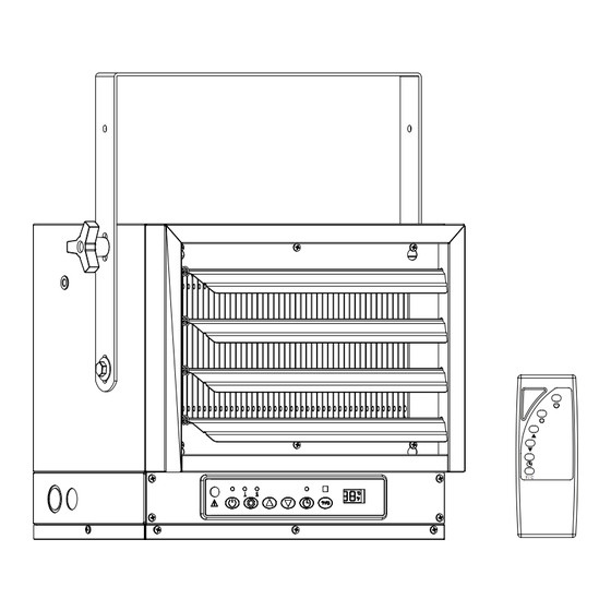
- Page 11 OPERATION INSTRUCTIONS Figure 11 A. Power Control B. Power Selection C. Temperature Selection D. Timer Selection E. °F /°C Display Selection F. LED Screen G. Caution Light...
- Page 12 OPERATION INSTRUCTIONS (CONTINUED) Figure 12 Control Panel Close-up Remote A. Power Control B. Power Selection C. Temperature Selection 1) TEMP+ : temperature up; 2)TEMP- : temperature down D. Timer Selection E. °F /°C Display Selection ° / ° F. LED Screen G.
- Page 13 OPERATION INSTRUCTIONS (CONTINUED) Setting The Timer The timer function allows you to set the length of operation from 1 to 12 hours. Each time the TIMER button is pressed the length of operation will increase an hour. The duration the timer is set for will be displayed on the LED screen in hour increments.
- Page 14 CARE AND MAINTENANCE (CONTINUED) Cleaning The Heating Element WARNING 1) To prevent possible electric shock, all power must be shut off at the main service before inspecting or cleaning. 2) To clean the heating element, loosen (but do not remove) the 4 Phillips head screws located behind the louvers in the corners of the louver housing on both sides, lift up and pull out (see Figure 13).
- Page 15 PARTS LIST QUANTITY PART# PART DESCRIPTION J03E-01 Handle J03E-02 Top Housing Back Housing J03E-03 Screw J03E-04 Screw Knobs J03E-05 Heating assembly J03E-06 J03E-07 Front Housing J03E-08 Electricity Box Cover Cover J03E-09 Electricity Box Housing J03E-10 Fan Blade J03E-11 Motor Housing J03E-12 Motor Bracket J03E-13...
- Page 16 ERROR CODE TROUBLESHOOTING GUIDE Error Code Possible Cause Recommended Solution Clearing Error Codes or the Insufficient clearance Ensure heater is installed with sufficient To clear E1 code or the caution light is on: caution light around heater clearance all-around: 1. Power off heater is on *8 feet minimum from floor 2.
- Page 17 ERROR CODE TROUBLESHOOTING GUIDE (CONTINUED) Error Code Possible Cause Recommended Solution Clearing Error Codes Moisture entrapment in Not intended for outdoor use. Not intended To clear E1 & codes: heater 1. Power off heater. Room for use in bathrooms, shower rooms, laundry 2.
- Page 18 (2) this device must accept any interference received, including interference that may cause undesired operation. The following responsible party designated in FCC §2.909 is responsible for this declaration: Model Number: SHAG-J03E Company Name: CM Development Inc. Company Address: P.O. Box 90962, CA 91715, USA...
Need help?
Do you have a question about the SHAG-J03E and is the answer not in the manual?
Questions and answers