Advertisement
Quick Links
Garage Ceiling Mounted Heater
PET OWNERS WARNING: Health warning for some small pets, including birds,
as they are extremely sensitive to the fumes produced during the first-time use
of many appliances.
These fumes are not harmful to humans but we recommend that you do not use
your heater around birds and small pets during its initial use until the manufacturing
corrosion (anti-corrosion) coatings burn off.
READ & SAVE THESE INSTRUCTIONS
Questions, problems, missing parts? Before returning the product,
EdithToynbee@outlook.com
MODEL: SHAG-J02M
ITEM: HGM-50
240V/60Hz, 5000W
please e-mail our customer service by
USER MANUAL
Advertisement

Related Manuals for HICFM SHAG-J02M


Summary of Contents for HICFM SHAG-J02M
- Page 1 USER MANUAL Garage Ceiling Mounted Heater MODEL: SHAG-J02M ITEM: HGM-50 240V/60Hz, 5000W PET OWNERS WARNING: Health warning for some small pets, including birds, as they are extremely sensitive to the fumes produced during the first-time use of many appliances. These fumes are not harmful to humans but we recommend that you do not use your heater around birds and small pets during its initial use until the manufacturing corrosion (anti-corrosion) coatings burn off.
- Page 2 IMPORTANT INSTRUCTIONS When using electrical appliances, basic precautions should always be followed to reduce the risk of fire, electrical shock, and injury to persons including the following: 1. Read all instructions before using this heater . 2. WARNING: In order to avoid overheating, do not cover the heater. 3.
- Page 3 IMPORTANT INSTRUCTIONS (CONTINUED) 17.This heater is designed to be directly wired to 240 volt electric power. Never use with an extension cord or relocatable power trap (outlet/power strip). 18.This heater may include an audible or visual alarm to warn that parts of the heater are getting excessively hot.
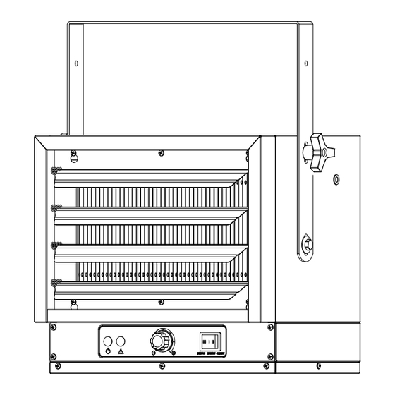
- Page 4 SPECIFICATIONS (CONTINUED) Caution light Heating element Overheat Power light AC240V/60Hz motor Temperature control Terminal station 4000W 3000W 5000W Switch Figure 2 WARNING: This applicance must be grounded! WARNING: Proper size fuses and circuit breakers in accordance with the National Electric Code must be used. WARNING: The applicance must be connected to a current protection circuit or device at 32-40 Amp before being connected to power supply!
- Page 5 GENERAL SAFETY INFORMATION WARNING: This heater requires hardwire installation (no plug). The installation of this product must be carried out by a certified electrician. Wiring procedures and connections shall be in accordance with the national and local codes having jurisdiction. NOTE: Compatible with a 240v line voltage double pole wall thermostat.
- Page 6 LOCATING THE HEATER Install heater out of traffic areas, maintaining clearances stated in figure 3. The direction of airflow should not be restricted by columns or machinery and the airflow should wipe exposed walls rather than blowing directly on them. When more than one heater is used in an area, the heaters should be installed so that the air discharge of each heater supports the air flow of the others, to provide best circulation of warm air as indicated in figure 4.
- Page 7 INSTALLATION Hardware needed You will also need the following hardware, which can be purchased from your local hardware store or electrical supply store: • Electric wire in the adequate gauge and length for your application; • Proper size fuse or breaker for your heater's amperage; •...
- Page 8 INSTALLATION (CONTINUED) Hanging The Heater 1) Lift the heater up and into the mounting bracket. 2) Align the bracket screws with the Keyhole slots in the mounting bracket. 3) If the heater is to be tilted, it must be positioned in the keyhole slots. (See figure 6) 4)Tighten the bracket screws with a wrench so the unit is securely suspended at horizontal or vertical level.
- Page 9 INSTALLATION (CONTINUED) Ceiling 90 degrees 67.5 degrees 45 degrees Figure 8 CONNECTING THE POWER 1. Remove the screws from the front of the heater to connect the power to the unit. 2. Attach the cable connectors to the unit (See Figure 9) and slide the 10-gauge wire through the cable connector.
- Page 10 CONNECTING THE POWER (CONTINUED) Conduit Connector If Heater is to be turned and Conduit wire is inside conduit. Flexible Conduit Flexible Conduit Connector If Heater is to be connected with NM Cable. Flexible NM Cable Flexible NM Cable Connector If Heater is to be connected with Flexible Conduit.
- Page 11 OPERATION INSTRUCTIONS Figure 11 A. Power Indicator (Amber) B. Thermostat C. Power Selection D. Caution Indicator (Red)
- Page 12 OPERATION INSTRUCTIONS (CONTINUED) Figure 12 Control Panel Close-up A. Power Indicator (Amber) B. Thermostat C. Power Selection D. Caution Indicator (Red) WARNING: the heater must be properly installed before it is used. Setting The Thermostat 1) When connect to the power supply, the amber POWER INDICATOR light will turn on. 2) After room reaches desired comfort level, rotate thermostat knob counterclockwise until a click is heard.
- Page 13 CARE AND MAINTENANCE 1. Before cleaning, make sure the power has been turned off at the circuit breaker panel and the heating element of the heater is completely cool. 2. To maintain the heater's appearance, it needs only to be wiped over occasionally with a dry duster.
- Page 14 CARE AND MAINTENANCE (CONTINUED) Cleaning The Fan And Motor WARNING 1) To prevent possible electric shock, all power must be shut off at the main service before inspecting or cleaning. 2) Remove the protective grille from the rear of the heater. This provides access to the fan and motor.
- Page 15 PARTS LIST QUANTITY PART# PART DESCRIPTION J02M-01 Handle J02M-02 Top Housing Back Housing J02M-03 Screw J02M-04 Screw Knobs J02M-05 Heating assembly J02M-06 J02M-07 Front Housing J02M-08 Electricity Box Cover Cover J02M-09 Electricity Box Housing J02M-10 Fan Blade J02M-11 Motor J02M-12 Motor Bracket J02M-13 Rear Grill...
Need help?
Do you have a question about the SHAG-J02M and is the answer not in the manual?
Questions and answers