Advertisement
Quick Links
Advertisement

Related Manuals for Verkada TD63


Summary of Contents for Verkada TD63
- Page 1 Install Guide TD63 Video Intercom...
- Page 2 Verkada product is granted under this document. This document may not be sold, resold, licensed or sublicensed and may not be transferred without Verkada’s prior written consent. No part of this document may be reproduced in whole or in part without the express written consent of Verkada.
- Page 3 Introduction Technical Specifications Sensor Resolution 5MP (2688 x 1944) Lens Type Fixed Image Sensor 1/2.8” Progressive CMOS Focal Length 2.12mm Iris Fixed Aperture F2.0 Field of View Horizontal: 130°, Vertical: 100°, Diagonal: 160° IR Range 15m / 50ft Onboard Storage 512GB Audio Streaming Two-way, full duplex with echo cancellation and noise suppression...
- Page 4 Introduction What’s in the box Junction Box Screws #6-32 (4 pcs) Length: 25.4mm Drive: #2 Phillips Junction Box Screws #8-32 (4 pcs) Length: 25.4mm Drive: #2 Phillips Video Intercom Mount Plate Surface Mount Box Mount Plate Screws M3x6mm (4 pcs) Length: 6mm Drive: T10 Wall Screws (4 pcs) Wall Anchors (4 pcs)
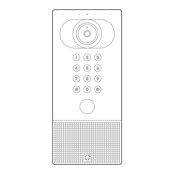
- Page 5 Introduction Overview (1/2) Status LED Camera Keypad Call Button Speaker Scan Area Status LED Behaviors Call Button LED Behavior Solid Orange Solid White Intercom is powered Intercom is on and booting up. Solid Green Flashing Orange Access granted Intercom is updating firmware. Solid Red Access denied Solid Blue...
- Page 6 Introduction Overview (2/2) I/O Connector PoE In Input / Output Ethernet (RJ45) Normally Closed Output Common Relay 1 Normally Open I/O Terminal Block Front Normally Closed Output Common Relay 2 Normally Open RS-485 A RS-485 RS-485 B Ground I/O Terminal Block Back Input 1 Inputs 1-3...
- Page 7 Note: This step can be done after mounting, although registering the product first will ensure it is in working order prior to mounting. Connect the TD63 to your network using the Ethernet port located behind the cable door on the device.
- Page 8 Preparation Mounting Options The Video Intercom can be mounted in either the Sub Flush Mounting configuration or the Surface Mounting configuration, using the Surface Mount Box. The following pages outline both installation options. Use the Sub Flush Mounting configuration for a lower profile installation where the intercom cable bay can sit inside the wall.
- Page 9 Installation Sub Flush Mounting (1/4) The mount plate has hole patterns for the following mounting conditions: A Direct wall mounting B 2-gang junction box mounting Use the (A) pattern to mount directly on to the wall, or (B) for 2-gang junction box.
- Page 10 Installation Sub Flush Mounting (2/4) Option 1: Direct Wall Mounting Use the mount plate as a template to mark mounting holes (A) and the center cutout. Drill 5/64 inch (2mm) pilot holes. If using wall anchors, drill 1/4" (6mm) pilot holes.
- Page 11 Installation Sub Flush Mounting (3/4) Option 1: Direct Wall Mounting Route the building-side cable through the hole in the center of the mount plate.
- Page 12 Installation Sub Flush Mounting (4/4) Option 2: 2-Gang Box Mounting For 2-gang box mounting, align the mount plate holes (B) with the junction box threads. Route the building-side cable through the hole in the center of the mount plate. Use the junction box screws to install the mount plate onto the junction box.
- Page 13 Installation Surface Mounting (1/3) The surface mount box has hole patterns for the following mounting conditions: A Direct wall mounting Use the (A) pattern to mount directly on to the wall Note: Do not use holes marked “2” in the surface mounting configuration.
- Page 14 Installation Surface Mounting (2/3) Use the surface mount box as a template to mark mounting holes (A) and the cable hole location. Drill 5/64 inch (2mm) pilot holes. If using wall anchors, drill 1/4" (6mm) pilot holes. For the cable, drill a 7/8" (22mm) hole when possible.
- Page 15 Installation Surface Mounting (3/3) Route the building-side cable through the hole. Attach the mount plate to the surface mount box with the included mount plate screws using the T10 Security Torx Screwdriver. Note: The cable should pass through the rectangular opening of Mount Plate, NOT the circular opening.
- Page 16 Installation Wiring (1/3) On the intercom, loosen the four T10 Security Torx screws on the cable bay door. Remove the cable bay door to access the Ethernet and I/O ports. Use the label on the interior of the cable bay door to choose which grommets to remove for wiring.
- Page 17 Installation Wiring (2/3) Route all the wires through the grommets and corresponding grommet holes. Remove the I/O terminal block for easier access to wiring. Attach the wires according to the labelling on the I/O terminal block. Relay 1 Relay 2 IN 3 IN 2 IN 1...
- Page 18 Installation Wiring (3/3) Plug in the RJ-45 and the I/O terminal block. Press the grommets back into the grommet holes on the cable bay door. Make sure the grommet is fully seated to ensure proper sealing. Note: The tail of the grommet should be facing away from the device after installation for proper sealing.
- Page 19 Installation Secure Guide the Intercom onto the two hooks on the top edge of the mount plate. Gently swing the bottom edge of the intercom down, against the mount plate. Secure the Intercom by tightening the two Security Torx screws at the bottom of the mount plate using the T10 Security Torx Screwdriver.
- Page 20 Option 1: Connect as an access controller The device can be setup as Fail Safe or Fail Secure with an external power source. Note: For ULC 60839-11-1 installations, release timing shall not be less than 3s. TD63 Terminal Block Access Power Controller Lock...
- Page 21 Option 2: Connect as an external badge reader The device can be setup as a standalone badge reader with an external Access Control Unit. Wire the terminal block to the ACU as shown below. TD63 Terminal Block Access Control Unit Reader Input...
- Page 22 Appendix TD63 Compliance 1/2 This device complies with Part 15 of the FCC Rules. Operation is subject to the following two conditions: Statement (1) This device may not cause harmful interference, and (2) this device must accept any interference received, including interference that may cause undesired operation.
- Page 23 Compliance to IEEE 802.3 This device accepts PoE type A or B. Use only UL listed class 2 power supply. Certification testing completed using PHIHONG TECHNOLOGY CO LTD Model POE60U-BTB (Verkada ACC-POE-60WHS) File E127643. PoE supply is for indoor use only.
- Page 24 Appendix Support Thank you for purchasing this Verkada product. If for any reason you're experiencing issues or need assistance, please contact our 24/7 Technical Support Team immediately. Sincerely, The Verkada Team verkada.com/support...
Need help?
Do you have a question about the TD63 and is the answer not in the manual?
Questions and answers