BraunAbility E Series Service Manual
International inboard lift, public use wheelchair lifts
Hide thumbs
Also See for E Series:
- Service manual (52 pages) ,
- Owner's manual (45 pages) ,
- Owner's manual (34 pages)
Table of Contents
Advertisement
Quick Links
Manufacturing Revision Level: Rev. A
Manufacturing Revision Level: Rev. A & B
www.braunability.com/international
Phone: +1 574 946 6153
404693 Rev. A
April
2019
Service Manual
International
Inboard Lift
E Series
Split Platform
Public Use
Wheelchair Lifts
EDEC08V74105L
EDEC08V86132L
631 West 11th Street, Winamac, IN 46996, USA
Original Instructions
ISO 9001:2015
Fax: +1 574 946 4670
Advertisement
Table of Contents

Related Manuals for BraunAbility E Series


Summary of Contents for BraunAbility E Series
- Page 1 Service Manual International Inboard Lift E Series Split Platform Public Use Wheelchair Lifts EDEC08V74105L Manufacturing Revision Level: Rev. A EDEC08V86132L Manufacturing Revision Level: Rev. A & B www.braunability.com/international ISO 9001:2015 631 West 11th Street, Winamac, IN 46996, USA Phone: +1 574 946 6153 Fax: +1 574 946 4670 404693 Rev.
-
Page 2: Warranty
Warranty Consult your local BraunAbility dealer regarding warranty policy. ® www.braunability.com/international BraunAbility ® INDIANA, USA BRAUNABILITY.COM XXXX Use Lift MODEL NUMBER Model No. XXXXXXX Max. Lifting Capacity - XXX lb SERIAL NUMBER Serial No. XXXXXXX MFG DATE Rev. XXXXXXX Date of Manufacture... -
Page 3: Table Of Contents
Contents Service Safety Precautions ..............2-3 Lift Specifications ..................4 Lift Terminology ..................5 Switch and Sensor Locations ..............6 Platform Fold Pressure Adjustment ............7 Platform Angle Adjustment ..............8 Tower Microswitch Adjustment ..............9 Static and Dynamic Tests ...............10-11 Maintenance and Lubrication ............12-16 Lift Electrical Schematic ..............17 Hydraulic Schematic ................18 Hydraulics Parts List ................20 Hydraulics Diagram ................21... -
Page 4: Service Safety Precautions
Service Safety Precautions Safety Symbols SAFETY FIRST! Know That ..The information contained in W ARNING C AUTION this manual and supplements (if included), is provided for your This symbol indicates This symbol indicates use and safety. Familiarity with important safety in- important information proper installation, operation, formation regarding a... - Page 5 Disconnect the power cable at the battery prior to servicing. Never modify (alter) a BraunAbility lift. Replacement parts must be BraunAbility authorized replacements. Never install screws or fasteners (other than factory equipped). Whenever replacing a hydraulic cylinder or seals, lower platform fully.
-
Page 6: Lift Specifications
Lift Specifications The lift must be installed, operated, and maintained as detailed in applicable manuals. Any use of equipment other than instructed in this manual is prohibited. The specifications below reflect CE standards. Lifts meet or exceed these requirements. Operating Temperature This equipment will operate in its intended ambient at a minimum between -30ºC and 65ºC. -
Page 7: Lift Terminology
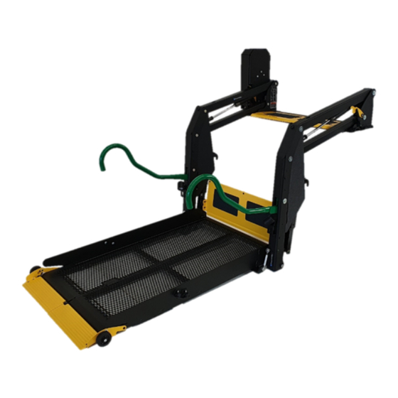
Lift Terminology Hand-Held Pendant Top Parallel Arms (2) Control Lift-Tite Latches (2) ™ Towers (2) Main Cylinders (2) Pump Module (Left) 3645 Base Plate Unfold Assist Compression Springs (2) Opposite Pump Side Vertical Arm Base Plate Cover Handrails (2) Bridge Plate Bottom Parallel Arms (2) Saddle (2) -
Page 8: Switch And Sensor Locations
Switch and Sensor Locations *Up & Unfold Microswitch Assy. 975-4121A *Partial Fold Microswitch *Up Microswitch 36884 *Unfold Microswitch 3645 Inboard Right (Front) *Note: Mirror image for right (front) pump lifts. Left (Rear) Outboard Inboard Front (of vehicle) (driver's side) Page 6 Rear Outboard (of vehicle) -
Page 9: Platform Fold Pressure Adjustment
7. Press Up/Fold on hand held pendant. Platform should not be able to fold. If platform continues To perform this adjustment, use BraunAbility to fold, lower platform back to floor level and #303206KS which contains the weight bracket turn the adjustment screw counter clockwise 1/4 turn. -
Page 10: Adjustment Procedure
Platform Angle Adjustment Figure C 36514 Lowering Sequence Requirements 1. The outboard end (toe) of the platform must contact Roll the ground first to ensure Stop the spring-loaded roll stop unfolds fully. See Figure C. Heel Ground Level 2. The inboard end (heel) of the platform must lower fully Roll stop must Platform heel... -
Page 11: Turnbuckle Adjustment
Turnbuckle Adjustment 1. Deploy platform to floor level. Be sure both adjustment screws are making full contact with the stop block (bars) in both vertical arms (Photo B). 36514 2. Both platform halves must be laying flat as shown in Figure F and Photo C. Adjust left turnbuckle so no tension is on the turnbuckle (adjust if needed only). -
Page 12: Tower Microswitch Adjustment
Tower Microswitch Adjustment W ARNING Figure G Improper microswitch adjustment may TOWER TOWER result in serious bodily injury and/or 32942 property damage. TOWER TOWER 36514 32942 TOWER TOWER Review adjustment Left (rear) pump lift depicted. Right procedures below and 32942 (front) pump lift is a mirrored image. -
Page 13: Static And Dynamic Tests
Static and Dynamic Tests Compatibility between the lift and the vehicle The installer shall confirm the compatibility between the lift and the vehicle. Static Test Deformation The unladen platform is positioned mid-way between ground level and vehicle floor level and measurements are taken of the height of the platform and its angular attitude relative to the vehicle floor. - Page 14 Static and Dynamic Tests Dynamic Test With 400 kg applied to the platform, verify that the lift is able to operate throughout its full range of normal lifting and lowering. 1. Lower platform to the ground. 2. Place 400 kg at center of platform. 3.
-
Page 15: Maintenance And Lubrication
Maintenance and Lubrication Lubrication Diagram Parallel Arm Lift-Tite Latch Tower Pivot Points ™ (2 Latches - 2 Points) Pivot Pin Bearings (16) Lift-Tite Latch Dampening Spring ™ (2 springs - 4 Points) Hydraulic Cylinder Pivot Bushings (8) 3645 Parallel Arm Pivot Pin Bearings (16) Handrail Pivot Pins (2) Bridge Plate Lever... -
Page 16: Maintenance And Lubrication Schedule
Maintenance and Lubrication Schedule 36513 36512 36514 Proper maintenance is necessary to ensure contaminants which W ARNING safe, trouble-free lift operation. Inspecting the lift could result in wear for any wear, damage or other abnormal condi- or damage to com- Maintenance and tions should be a part of the transit agency daily ponents. - Page 17 Maintenance and Lubrication Schedule Apply Light Oil - See Lubrication Diagram Platform turnbuckle pivot points (2 turnbuckles - 4 points) Apply Light Oil - See Lubrication Diagram Platform hinges 740mm (4) & 860mm (6) Correct or replace damaged parts. Inspect roll stop for proper operation Correct, replace damaged parts and/or Inspect roll stop latch feet for proper operation, Cycles...
- Page 18 Maintenance and Lubrication Schedule continued Replace damaged parts and resecure Inspect turnbuckle assemblies for wear as needed. See Turnbuckle adjustment or damage, proper operation and posi- section. tive securement. Resecure, replace or correct as Remove pump module cover and needed. inspect: 1500 •...
- Page 19 Maintenance and Lubrication Schedule 2000-53-EC Disassembly and Disposal Guidelines No lift components contain unacceptable amounts of lead, cadmium, mercury, or hexavalent chromium. 1. Lower platform to ground. Lift 2. Open pump module manual relief valve. Disposal Procedure 3. Disconnect power from lift. 4.
-
Page 20: Lift Electrical Schematic
Lift Electrical Schematic Notice: HAND-HELD DESCRIPTION SYMBOL PENDANT CONTROL 1. Shown with lift in stowed position. 2. Wire Identification Format: Wire Color - Size mm2 - Size AWG OR-0.326-22 3. All wires .518 mm (20 gauge) unless otherwise noted. BATTERY CHASSIS GROUND FOLD 0.326-22... -
Page 21: Hydraulic Schematic
Hydraulic Schematic Orifice Orifice Lifting Down Platform Fold Relief Relief Valve Valve Solenoid Valve 2500 Folding Relief Valve 1900 1200 Opposite Pump Side Pump Cylinder BACKUP PUMP Cylinder PUMP Description Symbol Description Symbol Fixed Displacement Hydraulic Port Pump 2 Way 2 Position Pump Motor Solenoid Valve Pressure Compensated... -
Page 22: Hydraulics Parts List
“Fold” Valve "Down” Valve (complete) (complete) Coil Coil #400783 #400783 NOTICE When adding or changing hydraulic fluid, use BraunAbility 32840-QT (Exxon Univis ® HVI 26) hydraulic fluid (do not Cartridge Cartridge mix with Dextron III or other #31121 #26078 hydraulic fluids). -
Page 23: Hydraulics Diagram
Hydraulics Diagram Hydraulic Repair For repair of a hydraulic hose or cylinder, read this. Service Bulletin 27049 Hydraulic Pump Motor Manual Backup Pump NOTICE Remove power from pump module and any spark source before working with hydraulic Use caution when working on fluid and components. -
Page 24: Pump Module Parts List
32873A * Apply Scotch-Weld Threadlocker Red TL71 (BraunAbility #11522-1) or equivalent to the (3) Button Head Screws (item 6) when retrofitting the hydraulic pump assembly. t Indicates items available for replacement part purposes only. These items are not included with replacement pump modules. -
Page 25: Pump Module Diagram
NOTICE NOTICE Remove power from pump Apply Scotch-Weld Thread- module and any spark source locker Red TL71 (BraunAbility before working with hydraulic Use caution when working on fluid and components. Wear #11522-1) or equivalent to components inside pump module. proper eye protection. Use... -
Page 26: Base Plate Assembly
Base Plate Assembly Exploded View Applicable Lift: EDEC08V74105L Page 24... - Page 27 NOTICE Applicable Lift: EDEC08V74105L - APPLY SCOTCH-WELD™ THREADLOCKER BLUE TL42 (BRAUNABILITY #18822) OR EQUIVALENT TO THREADS ON (4) IDENTIFIED SCREWS #24440 AND TORQUE TO 22.6 Nm (200 in lb). - APPLY SCOTCH-WELD™ THREADLOCKER RED TL71 (BRAUNABILITY #11522-1) OR EQUIVALENT TO THREADS ON ALL SCREWS #25527 AND (2) IDENTIFIED SCREWS #24440.
- Page 28 Base Plate Assembly Exploded View Applicable Lift: EDEC08V86132L Page 26...
- Page 29 NOTICE Applicable Lift: EDEC08V86132L - APPLY SCOTCH-WELD™ THREADLOCKER BLUE TL42 (BRAUNABILITY #18822) OR EQUIVALENT TO THREADS ON (4) IDENTIFIED SCREWS #24440 AND TORQUE TO 22.6 Nm (200 in lb). - APPLY SCOTCH-WELD™ THREADLOCKER RED TL71 (BRAUNABILITY #11522-1) OR EQUIVALENT TO THREADS ON ALL SCREWS #25527 AND (2) IDENTIFIED SCREWS #24440.
-
Page 30: Top Parallel Arm Assembly - Left / Right
S2) 404087KS - (NOT SHOWN) PIVOT PIN AND BEARING KIT - PARALLEL ARMS - E-SERIES ITEM PART NO. DESCRIPTION 402346 DECAL-BRAUNABILITY LOGO - DPA 24011 BEARING-FLANGE-3/4" X 3/8"-12FDU06 402804BKT ARM-PARALLEL-UPPER *BEARINGS INSTALLED, DECAL SHIPPED LOOSE, APPLY TO LEFT SIDE ARM AS SHOWN. -
Page 31: Bottom Parallel Arm Assembly - Left / Right
Applicable Lifts: NOTICE EDEC08V74105L EDEC08V86132L - APPLY SCOTCH-WELD™ THREADLOCKER RED TL71 (BRAUNABILITY #11522-1) OR EQUIVALENT TO THREADS ON SCREW #25527 AND TORQUE TO 25.4 Nm (225 in lb). SHIP OUT KITS PLEASE NOTE THAT NOT ALL PARTS ARE AVAILABLE SEPARATELY. -
Page 32: Hydraulic Cylinder Assembly
Hydraulic Cylinder Assembly Exploded View & Parts List Applicable Lifts: EDEC08V74105L EDEC08V86132L RETRACTED 57.617 cm (22.684 in) STROKE 32.106 cm (12.640 in) EXTENDED 89.723 cm (35.324 in) 30° ±10° SHIP OUT KIT PLEASE NOTE THAT NOT ALL PARTS ARE AVAILABLE SEPARATELY. S1) 403655KS - HYDRAULIC CYLINDER KIT - E-SERIES - LEFT &... -
Page 33: Vertical Arm Assembly - Left
Applicable Lifts: EDEC08V74105L EDEC08V86132L - APPLY SCOTCH-WELD™ THREADLOCKER RED TL71 (BRAUNABILITY #11522-1) OR EQUIVALENT TO THREADS ON SCREWS #25527 AND TORQUE TO 25.4 Nm (225 in lb). - TIGHTEN SCREW #81064-000 TO A TORQUE OF 11.8 Nm (105 in lb). -
Page 34: Vertical Arm Assembly - Right
Applicable Lifts: NOTICE EDEC08V74105L EDEC08V86132L - APPLY SCOTCH-WELD™ THREADLOCKER RED TL71 (BRAUNABILITY #11522-1) OR EQUIVALENT TO THREADS ON SCREWS #25527 AND TORQUE TO 25.4 Nm (225 in lb). - TIGHTEN SCREW #81064-000 TO A TORQUE OF 11.8 Nm (105 in lb). -
Page 35: Fold Arm Assembly - Left
Fold Arm Assembly - Left Exploded View & Parts List Applicable Lifts: EDEC08V74105L EDEC08V86132L SHIP OUT KIT PLEASE NOTE THAT NOT ALL PARTS ARE AVAILABLE SEPARATELY. S1) 403265AKS - INNER/OUTER FOLD ARM KIT COMPLETE- E-SERIES - LEFT ITEM PART NO. DESCRIPTION 404033 SPRING-IB SADDLE... -
Page 36: Fold Arm Assembly - Right
Fold Arm Assembly - Right Exploded View & Parts List Applicable Lifts: EDEC08V74105L EDEC08V86132L SHIP OUT KIT PLEASE NOTE THAT NOT ALL PARTS ARE AVAILABLE SEPARATELY. S1) 403264AKS - INNER/OUTER FOLD ARM KIT COMPLETE- E-SERIES - RIGHT ITEM PART NO. DESCRIPTION 404033 SPRING-IB SADDLE... -
Page 37: Handrail Assembly
Exploded View & Parts List Applicable Lift: NOTICE EDEC08V74105L - APPLY SCOTCH-WELD™ THREADLOCKER RED TL71(BRAUNABILITY #11522-1) OR EQUIVALENT TO THREADS ON SCREW #404059. - LEFT HANDRAIL SHOWN, ITEMS 3, 4, 5, 8 AND 9 ARE MIRROR IMAGE FOR RIGHT HANDRAIL. SHIP OUT KIT PLEASE NOTE THAT NOT ALL PARTS ARE AVAILABLE SEPARATELY. - Page 38 Exploded View & Parts List Applicable Lift: NOTICE EDEC08V86132L - APPLY SCOTCH-WELD™ THREADLOCKER RED TL71(BRAUNABILITY #11522-1) OR EQUIVALENT TO THREADS ON SCREW #404059. - LEFT HANDRAIL SHOWN, ITEMS 3, 4, 5, 8 AND 9 ARE MIRROR IMAGE FOR RIGHT HANDRAIL. SHIP OUT KIT PLEASE NOTE THAT NOT ALL PARTS ARE AVAILABLE SEPARATELY.
- Page 39 Notes This page intentionally left blank. Page 37...
-
Page 40: Platform Left Half Assembly
NOTICE Applicable Lift: EDEC08V74105L - APPLY SCOTCH-WELD™ THREADLOCKER BLUE TL42 (BRAUNABILITY #18822) OR EQUIVALENT TO THREADS ON SCREW #30375WP AND TORQUE TO 6.8 Nm (60 in lb). - TIGHTEN SCREWS #17192P TO A TORQUE OF 6.8 Nm (60 in lb). -
Page 41: Platform Right Half Assembly
NOTICE Applicable Lift: EDEC08V74105L - APPLY SCOTCH-WELD™ THREADLOCKER BLUE TL42 (BRAUNABILITY #18822) OR EQUIVALENT TO THREADS ON SCREW #30375WP AND TORQUE TO 6.8 Nm (60 in lb). - TIGHTEN SCREWS #17192P TO A TORQUE OF 6.8 Nm (60 in lb). -
Page 42: Platform Left Half Assembly
NOTICE Applicable Lift: EDEC08V86132L - APPLY SCOTCH-WELD™ THREADLOCKER BLUE TL42 (BRAUNABILITY #18822) OR EQUIVALENT TO THREADS ON SCREW #30375WP AND TORQUE TO 6.8 Nm (60 in lb). - TIGHTEN SCREWS #17192P TO A TORQUE OF 6.8 Nm (60 in lb). -
Page 43: Platform Right Half Assembly
NOTICE Applicable Lift: EDEC08V86132L - APPLY SCOTCH-WELD™ THREADLOCKER BLUE TL42 (BRAUNABILITY #18822) OR EQUIVALENT TO THREADS ON SCREW #30375WP AND TORQUE TO 6.8 Nm (60 in lb). - TIGHTEN SCREWS #17192P TO A TORQUE OF 6.8 Nm (60 in lb). -
Page 44: Edec08V74105L )
Applicable Lift: NOTICE EDEC08V74105L - APPLY SCOTCH-WELD™ THREADLOCKER RED TL71 (BRAUNABILITY #11522-1) OR EQUIVALENT TO THREADS ON ALL SCREWS #25527.. - APPLY SCOTCH-WELD™ THREADLOCKER BLUE TL42 (BRAUNABILITY #18822) OR EQUIVALENT TO THREADS ON BOLTS #402410 AND TORQUE TO 22.5 Nm (200 in lb). - Page 45 Platform Base Assembly Parts List Applicable Lift: EDEC08V74105L ITEM PART NO. DESCRIPTION 18657 RING-3/4" RETAINING SNAP 13889 RING-3/8" RETAINING SNAP 402957BK IB LEVER 83589-2 WASHER-.390" ID X .75" OD X .062" NYLON 24028 BEARING-PLASTIC FLANGE 3/8" ID X 1/4" 403055 FOLD ARM SPACER-UHMW 24174-BK TRACTION GRIP-6"...
-
Page 46: Edec08V86132L )
NOTICE Applicable Lift: EDEC08V86132L - APPLY SCOTCH-WELD™ THREADLOCKER RED TL71 (BRAUNABILITY #11522-1) OR EQUIVALENT TO THREADS ON ALL SCREWS #25527.. - APPLY SCOTCH-WELD™ THREADLOCKER BLUE TL42 (BRAUNABILITY #18822) OR EQUIVALENT TO THREADS ON BOLTS #402410 AND TORQUE TO 22.5 Nm (200 in lb). - Page 47 Platform Base Assembly Parts List Applicable Lift: EDEC08V86132L ITEM PART NO. DESCRIPTION 18657 RING-3/4" RETAINING SNAP 13889 RING-3/8" RETAINING SNAP 402957BK IB LEVER 83589-2 WASHER-.390" ID X .75" OD X .062" NYLON 24028 BEARING-PLASTIC FLANGE 3/8" ID X 1/4" 403055 FOLD ARM SPACER-UHMW 24174-BK TRACTION GRIP-6"...
-
Page 48: Decals And Antiskid
Failure to do so may result in serious bodily injury and/or 402346 property damage. Decal, BraunAbility Logo-QLD DPA 37589 (70 mm x 140 mm - 4" x .875") 37589 Decal, Warn, Hydraulic Press Adj, Intl, CE (50 mm x 53 mm - 1.98" x 2.08") - Page 49 Decals and Antiskid 402347 Rev B 402347 Decal, Authorized Rep, QC Inspect - Autoadapt, Intl, CE (51 mm x 106 mm - 2" x 4.156") 402527 402527 Decal, Manual OP-QLD DPA (70 mm x 140 mm - 2.75" x 5.5") TOWER TOWER 32942...
-
Page 50: Declaration Of Conformity
Product Certificate BraunAbility Europe AB Declaration of Conformity Issued by BraunAbility Safety Centre in Stenkullen, Sweden. Manufacturer: The Braun Corporation Address: 631 West 11th Street, Winamac, IN 46996 United States Authorized Representative and Importer into EU: Manufacturer: BraunAbility Europe AB Address: Åkerivägen 7, 443 61 Stenkullen, Sweden... - Page 51 Notes This page intentionally left blank. Page 49...
- Page 52 April 2019 Braun® is a registered trademark of BraunAbility® All illustrations, descriptions and speci cations in this document are based on the latest product information available at the time of publication. The Braun Corporation reserves the right to make changes at any time without notice.
Need help?
Do you have a question about the E Series and is the answer not in the manual?
Questions and answers