Advertisement
Quick Links
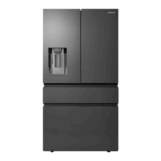
REFRIGERATOR
Premium Plus I&W [BASIC]
REFRIGERATOR
FRENCH DOOR REFRIGERATOR
MODEL NAME :
MODEL CODE :
RF23M8090SR/AA
RF23M8090SG/AA
RF23M8070SR/AA
RF23M8070SG/AA
RF23M8080SR/SA
RF23M8090SG/SA
RF23M8080SR/EU
1. PRECAUTIONS (SAFETY WARNINGS)······ 3
2. MODEL CODE TABLE
3.
DISASSEMBLY AND REASSEMBLY ········ 7
4.
TROUBLESHOOTING ······························ 41
5.
PBA DIAGRAM ····································
6.
WIRING DIAGRAM ······························
7.
BLOCK DIAGRAM ································
Masstige I&W
RF23M80*0**
RF23M8080SR/EF
RF23M8090SG/EF
RF23M8080SR/EE
RF23M8080SR/ML
RF23M8080SR/CL
CONTENTS
··························· 6
87
92
93
2017. 4. 11.
4:53
Advertisement


Need help?
Do you have a question about the RF23M80 0 Series and is the answer not in the manual?
Questions and answers
Is there a part number for the gasket/seal that is attached to the left door of the fridge and seals the ice box