Advertisement
Quick Links
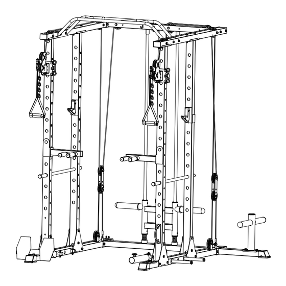
ASSEMBLY INSTRUCTIONS
2x NOT INCLUDED
NOTE:DO NOT FULLY
TIGHTEN HARDWARE
UNTIL FINAL STEP
MEET ANY QUESTION ASSEMBLING OR PRODUCT?
MIKOLO RECOMMENDS TWO PEOPLE
EMAIL US FOR CUSTOMER SERVICE
NEEDED TO ASSEMBLE THIS CAGE I
N FLAT GROUND.
after-sale@mikologym.com
www.mikologym.com
Advertisement

Related Manuals for Mikolo RSI-K3


Summary of Contents for Mikolo RSI-K3
- Page 1 ASSEMBLY INSTRUCTIONS 2x NOT INCLUDED NOTE:DO NOT FULLY TIGHTEN HARDWARE UNTIL FINAL STEP MEET ANY QUESTION ASSEMBLING OR PRODUCT? MIKOLO RECOMMENDS TWO PEOPLE EMAIL US FOR CUSTOMER SERVICE NEEDED TO ASSEMBLE THIS CAGE I N FLAT GROUND. after-sale@mikologym.com www.mikologym.com...
- Page 2 Read all precautions and instructions in this manual before using this equipment Summary Part List Hardware List Step Overview Step 1-2 (Base) Step 3-5 (Upright Rod) Step 6 (Cable) Step 7 (Weight Holder) Step 8 (Pull up Bar) Step 9-10 (Pulley) Step 11-12 (Cable) Step 13 (Attachments) www.mikologym.com...
- Page 3 ASSEMBLY Make Things Easier for Yourself Everything in this manual is designed to ensure that the weight system can be assembled suc-cessfully by anyone.However, it is important to realize that the versatile weight system has many parts and that the assembly process will take time.
- Page 4 PARTS LIST www.mikologym.com...
- Page 5 HARDWARE LIST www.mikologym.com...
- Page 6 STEP Build Basic Cage Frame STEP 6-10 Add On Pulley System STEP 11-13 Add On Attachments www.mikologym.com...
- Page 7 STEP: 1 1.Bolt M10*95 2.Bolt M10*90 6.Bolt M10*30 7.Washer M10 8.Lock Nut M10 2 PCS 2 PCS 2 PCS 10 PCS 4 PCS A1.Base Rod(LEFT) A2.Base Rod(RIGHT) A3.Rear Base Rod 1PCS 1PCS 1PCS A4.Weight Storeage A5.Weight Storeage Rack Base Rack 1PCS 1PCS www.mikologym.com...
- Page 8 STEP: 2 A6.Footboard A8.Landmine 6.Bolt M10*30 7.Washer M10 4 PCS 4 PCS 1 PCS 1 PCS www.mikologym.com...
- Page 9 STEP: 3 1.Bolt M10*95 7.Washer M10 8.Lock Nut M10 B1.Connection Piece 8 PCS 16 PCS 8 PCS 8 PCS www.mikologym.com...
- Page 10 STEP: 4 B4.Pulley Sliding B5.Pulley Sliding Sleeve(LEFT) Sleeve(RIGHT) 1 PCS 1 PCS B2.Front Upright Rod B3.Rear Upright Rod 1PCS 1PCS www.mikologym.com...
- Page 11 STEP: 5 1.Bolt M10*95 7.Washer M10 8.Lock Nut M10 8 PCS 16 PCS 8 PCS www.mikologym.com...
- Page 12 STEP: 6 4.Bolt M10*70 7.Washer M10 8.Lock Nut M10 8 PCS 16 PCS 8 PCS B2.Front Upright Rod B3.Rear Upright Rod C1.Upper Side Frame 1PCS 1PCS 1PCS www.mikologym.com...
- Page 13 STEP: 7 D2.Weight Holder D3.Shock Pad D4.Bufferspring 1 PCS 2 PCS 2 PCS A3.Rear Base Rod D1.Guide Rod 1PCS 1PCS www.mikologym.com...
- Page 14 STEP: 8 2.Bolt M10*90 7.Washer M10 8.Lock Nut M10 6.Bolt M10*30 8 PCS 16 PCS 8 PCS 2 PCS C2.Pull Up Frame C3.Rear Upper Frame D1.Guide Rod 1PCS 1PCS 1PCS www.mikologym.com...
- Page 15 STEP: 9 5.Bolt M10*45 7.Washer M10 8.Lock Nut M10 9.Pulley 10.Plastic Liner 8 PCS 16 PCS 8 PCS 8 PCS 16 PCS www.mikologym.com...
- Page 16 STEP: 10 6.Bolt M10*30 7.Washer M10 8.Lock Nut M10 9.Pulley 5 PCS 10 PCS 5 PCS 5 PCS www.mikologym.com...
- Page 17 STEP: 11 NAME SPECIFICATIONS FIGURE SHOWS Schematic Diagram Of Wire Rope Routing In Birds Wire Rope (508Inch)X1 www.mikologym.com...
- Page 18 STEP: 12 NAME SPECIFICATIONS FIGURE SHOWS Diagram Of Transition Wire Rope Routing Transition (141Inch)X2 Wire Rope www.mikologym.com...
- Page 19 STEP: 13 3.Bolt M10*75 7.Washer M10 8.Lock Nut M10 A7.Band Peg B11.Battle Rope Ring 2 PCS 4 PCS 2 PCS 4 PCS 1PCS B6.Dip Bar B6.Dip Bar B8.J Hook B9.J Hook B10.Safety Bar (LEFT) (RIGHT) (LEFT) (RIGHT) 1 PCS 1 PCS 1 PCS 1 PCS 1PAIR...
Need help?
Do you have a question about the RSI-K3 and is the answer not in the manual?
Questions and answers