
Related Manuals for Blueview TCHARGE UDC 360


Summary of Contents for Blueview TCHARGE UDC 360
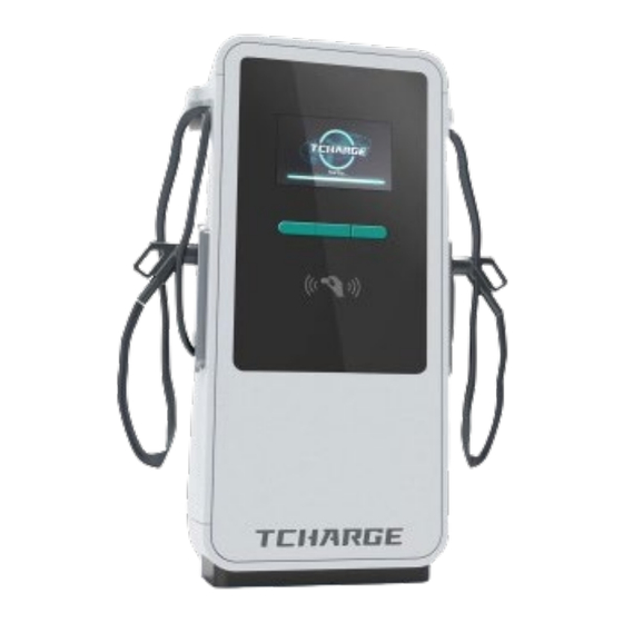
- Page 1 TCHARGE UDC 360 DCFC Charger ® Installation Manual Charger Installation Manual UDC 360 DCFC...
-
Page 2: Copyright Information
Trademarks TCHARGE is a trademark of BLUEVIEW ELECTRICITY INC. (BLUEVIEW) registered in the United States; ® TCHARGE TUCHONG are trademarks of TUCHONG TECHNOLOGY CO., LTD (TUCHONG) registered ® ® in China. All other marks are trademarks or registered trademarks of their respective holders. -
Page 3: Safety Information
Safety Instructions The safety messages herein cover situations BLUEVIEW is aware of. BLUEVIEW cannot know, evaluate, or advise you as to all the possible hazards. You must be certain that any condition or service procedure encountered does not jeopardize anyone’s personal safety. - Page 4 CAUTION Do not use private power generators as a power source for charging electric vehicles (EVs) with this device. Do not operate the device in temperatures outside its working temperature range. Incorrect installation, operation, or testing of the device could potentially damage the battery or other components of an EV as well as the charger device itself.
-
Page 5: Table Of Contents
Contents 1. Using This Manual ......................1 1.1 Purpose ........................1 1.2 Applicable Products ....................1 1.3 Definition of Warning Symbols ................1 2. General Introduction ....................... 2 2.1 Intended Uses ......................2 2.2 Product Overview ....................3 2.3 Key Technical Parameters ..................6 3. -
Page 6: Using This Manual
1. Using This Manual 1.1 Purpose The purpose of this manual is to offer guidance regarding on-site installation and use of TCHARGE ® UDC 360 DCFC charger. 1.2 Applicable Products This document applies to TCHARGE UDC 360 DCFC charger. ® Caution: Death, injury, and/or property damage may occur if you use this equipment in a manner other than as described in this manual or other related documents. -
Page 7: General Introduction
2. General Introduction TCHARGE DCFC charger is designed to charge an electric vehicle (EV). Our chargers provide you with ® safe, reliable, fast, and smart EV charging solutions. This manual will instruct users and installation technicians on how to install this charger. 2.1 Intended Uses TCHARGE UDC 360 DCFC charger is suitable for charging EVs with 3-phase AC power input and DC... -
Page 8: Product Overview
2.2 Product Overview 2.2.1 TCHARGE UDC 360 DCFC Charger Product Dimensions ® Figure 2.1 TCHARGE UDC 360 DCFC Charger Dimensions Overview ® 2.2.2 TCHARGE UDC 360 DCFC Charger Block Diagrams ® Below is a structural diagram of TCHARGE UDC 360 DCFC charger. The 360kW configuration with 12 ®... - Page 9 Figure 2.2 TCHARGE UDC 360 DCFC Charger 360kW Block Diagram ® Charger Installation Manual UDC 360 DCFC...
- Page 10 Code Component Code Component Molded case circuit breaker Shunt current Micro circuit breaker Charge protocol interface AC surge-protection device Insulation monitor interface Auxiliary power supply (AC to DC) DC Meter LED strip Charger controller board DC fuse Touchscreen Cooling fan IO controller board Power module AC grid connection...
-
Page 11: Key Technical Parameters
2.3 Key Technical Parameters General Design Dimension (H*W*D) 71" H * 32" W * 33" D (1800mm * 800mm * 850mm) Weight 1,058 lb. (480kg) (max., lighter for models with less than 360kW output) 360kW / 400A (max.); 200kW / 200A max. output for each charging port when Output Rating &... -
Page 12: Before Installation
3. Before Installation 3.1 Receiving the Charger Upon receiving the charger, please unpack and examine the charger with following procedures: Check the charger’s nameplate and packing list; crosscheck with your purchase orders to verify that you receive the correct numbers and models of equipment. If there are any discrepancies, please contact both TCHARGE and the shipping carrier(s) to follow the problem. -
Page 13: Planning Installation Site
3.4 Planning Installation Site Figure 3.1 Dimensions and Space Requirement Around TCHARGE UDC 360 DCFC Charger ® Before installation of TCHARGE UDC 360 DCFC charger, please consider the following factors for ® spaces on the projected installation site: The front door of the cabinet requires at least 30 inches of empty space in the front of the charger to be fully opened. -
Page 14: Install The Charger
4. Install the Charger 4.1 Prepare the Foundation 4.1.1 Prepare the Foundation Pit At the site where the charger is intended to be installed, make a pit in the ground to hold the concrete foundation for the charger. Leave tunnel(s) on at least 1 side of the foundation as an inlet for cables. Dimension of the pit should be: ... - Page 15 4.1.2 Form the Foundation 1) Before forming the foundation, place the cable conduit for incoming cables (including power cables and ethernet cable) to go through the foundation pit via the cable tunnel. Choice and placement of the cable duct should follow the dimensions depicted in Figure 4.2: ...
- Page 16 Figure 4.2 Placing Incoming Cable Conduit and Forming Foundation (Front and Right Views) DCFC Charger Installation Manual UDC 360...
-
Page 17: Installing The Cabinet
4.2 Installing the Cabinet Caution Professional hoisting equipment and personnel are required for conducting hoisting operations on the charger. 1) On the top surface of the concrete foundation (prepared in Part 4.1), drill holes for the M-12 expansion bolts that would be used to fix the charger to the foundation. Refer to Figure 4.3 below for relative positions of the holes (red circles): ... - Page 18 Drilling template (provided with the charger) Figure 4.4 Drill Screw Holes with Drilling Template TCHARGE Section 2) After transporting the UDC 360 DCFC charger to the installation site (see ® for more information on transporting the charger), open the covers on the sides of the pedestal (bottom section) of the charger for access installation positions of expansion bolts.
- Page 19 3) Check if the 4 eyebolts are already installed on the top of the charger to form the lifting loops (marked as B in Figure 4.6). If the eyebolts are shipped separately, install them in the holes on top of the charger first. Connect the hoisting equipment to these lifting loops and hoist the charger to remove it from the shipping pallet (Figure 4.6 left).
- Page 20 4x M12 Expansion Bolts Figure 4.7 Fix the Charger on Top of the Concrete Foundation 6) Side covers of pedestal can be restored once all following conditions are met: All the M12 expansion bolts are duly fastened. Charger is standing steadily upright. ...
-
Page 21: Wiring
4.3 Wiring 4.3.1 Install Adapter Ring TCHARGE UDC 360 series DCFC charger has an “adapter ring” design at the cable inlet of the charger. ® A circle shaped steel pad can be installed on the inlet with 4 screws. The inner diameter of the circle pad can be customized, allowing the size of the cable inlet to always match the actual size of cable conduit, leaving minimum gap between the edge of inlet and outer surface of conduit. - Page 22 4.3.2 Wiring Warning! Electricity is dangerous and electrical procedures can be fatal. Operations in this section should only be carried out by qualified professional electricians who fully understand the procedures and can ensure on-site safety. 1) After directing wires to enter TCHARGE UDC 360 DCFC charger’s cabinet box from the cable ®...
- Page 23 Figure 4.9 Earth Wire (GND) and Neutral Wire Terminals Figure 4.10 Hot Wire Terminals Note Based on specific requirements of project sites, TCHARGE team may use ® different versions of design for TCHARGE UDC 360 series DCFC charger’s ® wiring terminals. If the design of terminals on your charger is different from the ones depicted in Figure 4.9 &...
-
Page 24: Internet Hardware Connections
4.3.3 Fireproof Mud Sealing After all wiring processes are finished, seal the gap between the cable inlet hole’s edge and the conduit with fireproof mud. This is to ensure that no creatures or foreign matters goes into the charger’s cabinet box while the charger is put into operation, causing unwanted accidents. For a diagram of the gap needed to be sealed, please see Figure 4.11 below. - Page 25 In the event that you would like to install the ethernet cable and/or 4G SIM card after putting the charger into use, please remember to cut off the AC power supply before installation of these hardware! Important Note The AC input hotwires of TCHARGE UDC 360 series DCFC charger typically ®...
- Page 26 Figure 4.12 RJ45 Port, SIM Card Slot, and Other Ports on the Touch Screen Control Board Figure 4.13 Install SIM Card in SIM Card Socket (Front View & Back View) DCFC Charger Installation Manual UDC 360...
-
Page 27: Service And Support
5. Service and Support If you encounter any problem while installing or using the charger, please contact our technical support. For services in U.S. or Canada, please contact BLUEVIEW with the following information: Web: http://www.blueview-usa.com/ Email: support@blueviewelectricity.com 6. Compliance Information The product is in conformity and certified with the following technical standards: ...
Need help?
Do you have a question about the TCHARGE UDC 360 and is the answer not in the manual?
Questions and answers