
Subscribe to Our Youtube Channel
Related Manuals for ZIEHL-ABEGG ZAtop SM315.100A


Summary of Contents for ZIEHL-ABEGG ZAtop SM315.100A
- Page 1 english M o v e m e n t b y P e r f e c t i o n ZAt o p Gearless elevator machine S M 3 15. 100A Issue 2024/27 Original operating instructions Store for future use! A-TBA22_02-GB 2024/27 Index 003 | 01013486-GB...
- Page 2 Original operating instructions Table of contents Table of contents Introduction Liability Validity and meaning of the instructions Target group of the operating instructions Applicable documents Safety instructions Intended use Requirements placed on the personnel Live parts 2.4 Powerful magnetic fields DO NOT reach into the rope retainer Do not touch the ropes Rotating parts Automatic restart...
- Page 3 Original operating instructions Table of contents Electrical installation Connecting the elevator machine Connecting the shielding for the motor cable Connecting temperature monitoring devices Connecting additional protective conductors Connect the absolute encoder Connection and cable length of the absolute encoder Contact assignment absolute encoders ECN1313 EnDat and ECN1313 SSI Contact assignment absolute encoder AE-S64-BISSC-ZA-5m/AE-S64-SSI-ZA-10m Contact assignment absolute encoder ERN1387 6.10 Contact assignment, absolute encoder AE-S64-SinCos-AE-7m...
- Page 4 14.3 Degree of protection 14.4 Ambient conditions 14.5 Brake RSD9 14.6 Inductive proximity switch 14.7 Microswitch 14.8 Forced ventilation 14.9 Dimension sheet ZAtop SM315.100A 14.10 Dimension sheet with Bowden cable system 14.11 Legend for dimension sheets 4/88 A-TBA22_02-GB 2024/27 Index 003...
- Page 5 These instructions apply to ZAtop SM315.100A elevator machines. The model range can be identified by the type designation, see Motor rating plate, page 12. These instructions apply only to the product ZIEHL-ABEGG SE and not to the complete system. If additional devices are used or installed, the respective instructions must be observed.
- Page 6 Original operating instructions Safety instructions Personnel Minimum requirements, knowledge and experience Planners and project de- They are responsible for the project planning of the complete system. They have signers knowledge of applicable standards, legal requirements and safety regulations. Transport personnel They can deal safely with industrial trucks, loads and transport regulations.
- Page 7 2.9 Modifications and spare parts Unauthorised modifications and unauthorised spare parts can lead to serious injuries. Z Do not modify the device. Z Before making changes, obtain written approval from ZIEHL-ABEGG SE. Z Use spare parts from ZIEHL-ABEGG SE. 2.10 Do not disassemble components Dismantling components leads to safety gaps during operation. This may result in severe injuries.
- Page 8 Z Observe the specified ambient temperatures, see Ambient conditions, page 83. Z Observe the specified air humidity, see Ambient conditions, page 83. 2.20 Subsequent coating The product may be damaged by subsequent coating. Z Do NOT coat the product without consulting ZIEHL-ABEGG SE. 3 Transport and storage Personnel qualifications: Transport personnel 3.1 Transport 8/88 A-TBA22_02-GB 2024/27 Index 003...
- Page 9 Original operating instructions Transport and storage WARNING Crushing hazard due to suspended loads and uncontrolled moving parts. Z Wear safety helmet, safety gloves and safety shoes. Z Only move loads under supervision. Z Do NOT walk or reach under suspended loads. Z Set down the load when you leave the work area.
- Page 10 Original operating instructions Transport and storage Alternative Procedure: 1. Transport the product in its original packaging on the pallet. 2. Unpack the product. 3. Check the product for damage. 4. Select the lifting gear according to the weight on the rating plate. 5.
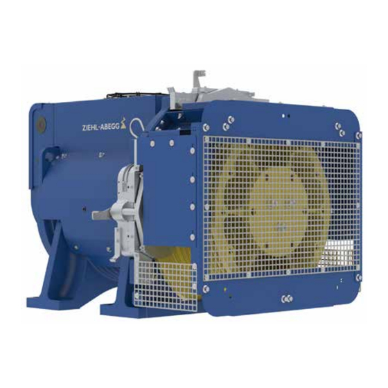
- Page 11 Original operating instructions Product overview 4 Product overview 4.1 ZAtop SM315 Forced ventilation, optional Suspension point Brakes RSD9 Housing elevator machine Terminal box Traction sheave Absolute encoder connection cover Traction sheave cover with rope retainer Absolute encoder 11/88 A-TBA22_02-GB 2024/27 Index 003...
- Page 12 Original operating instructions Product overview 4.2 Motor rating plate Example of motor rating plate: Hologram Acceleration current Motor number Degree of protection QR code Weight Product certification CE mark Trips per hour Number of poles On time as per IEC Product certification UK CA mark Mode Date of manufacture...
- Page 13 Original operating instructions Installation The brakes do not wear if the brakes are used only as a holding brake. The more often the brakes are used for an EMERGENCY STOP, the greater the wear on the friction lining. The air gap must be checked on all brakes. Traction sheave The traction sheave is the rope carrier of the elevator machine.
- Page 14 Original operating instructions Installation 7. Position the elevator machine. 300mm To facilitate connection, maintain a distance of at least 300 mm behind the elevator machine. For the air flow of the forced ventilation, a distance of at least 200 mm must be maintained above it. If the distance cannot be maintained, the forced ven- tilation function will be impaired.
- Page 15 Original operating instructions Electrical installation 1. Place the ropes on the traction sheave (2). ATTENTION! Material damage due to incorrect rope pull force. Z If the traction sheave has more grooves than there are ropes, place the ropes in the centre or towards the elevator machine housing.
- Page 16 Original operating instructions Electrical installation 6.1 Connecting the elevator machine Prerequisite: ▫ Length of motor cable: maximum 25 m ▫ Shielded lines Procedure: 1. Connect the frequency inverter (1) in the correct phase according to the connection diagram. 2. Connect the motor temperature monitoring (2) ac- cording to the connection diagram.
- Page 17 Original operating instructions Electrical installation 3. Unscrew one of the fixing screws (6) on the metal strap (5). 4. Position the motor cable (4). The metal strap (5) must make contact with the exposed part of the mo- tor cable (4). 5. Tighten the metal strap (5) with the fixing screw (6) to 2.8 Nm. 6. Connect the temperature monitoring, see Connect- ing temperature monitoring devices, page 17.
- Page 18 Original operating instructions Electrical installation 6.4 Connecting additional protective conductors The motor cable's protective conductor must have a cross-section of at least 10 mm². Otherwise, a 2nd protective conductor must be connected. Prerequisite: The cross-section of the 2nd protective conductor corresponds at least to the cross-section of the motor cable's protective conductor.
- Page 19 Original operating instructions Electrical installation ▫ Shielded lines Procedure: 1. Use the supplied cable or design a corresponding cable, see contact assignments of the existing absolute en- coder: - Contact assignment absolute encoders ECN1313 EnDat and ECN1313 SSI, page 19 - Contact assignment absolute encoder AE-S64-BISSC-ZA-5m/AE-S64-SSI-ZA-10m, page 20 - Contact assignment absolute encoder ERN1387, page 20 - Contact assignment, absolute encoder AE-S64-SinCos-AE-7m, page 21...
- Page 20 Original operating instructions Electrical installation Plug Plug Plug Function Description ZIE- ZIE- Heiden- HL-ABEGG HL-ABEGG hain M16 x 0.75 D-SUB M23 x 1 SV 120 15-pole CLOCK- Clock line inverse CLOCK+ Clock line for serial transfer Sensor 0 V Sensor cable, absolute encoder voltage, negative Analog track A cosine Analog track A cosine inverse Analog track B sine inverse...
- Page 21 Original operating instructions Electrical installation Plug Plug Plug Function Description ZIE- ZIE- Heiden- HL-ABEGG HL-ABEGG hain M16 x 0.75 D-SUB M23 x 1 SV 120 15-pole Commutation signal sine inverse Reference signal Reference signal inverse Analog track A cosine Analog track A cosine inverse Analog track B sine inverse 6.10 Contact assignment, absolute encoder AE-S64-SinCos-AE-7m...
- Page 22 Original operating instructions Electrical installation ▫ See Installation and settings for inductive proximity switches Adjusting and mounting inductive proximity switch- es, page 76. ▫ See technical data Microswitch, page 83. ▫ See Installation and settings for microswitches Setting and assembling microswitches, page 80 6.12 Connecting the brake The brake terminal box can be mounted on both sides for better accessibility.
- Page 23 Original operating instructions Electrical installation Connection diagram with inductive proximity switch V123 Brake 1 Terminals: 1 and 2 Brake release monitoring brake 1 Terminals: 3 to 5 Brake 2 Terminals: 6 and 7 Brake release monitoring brake 2 Terminals: 8 to 10 Brake 3 Terminals: 11 and 12 Brake release monitoring...
- Page 24 Original operating instructions Electrical installation Connection diagram with microswitch V127 Brake 1 Terminals: 1 and 2 Brake release moni- toring brake 1 Terminals: 3 to 5 Brake 2 Terminals: 6 and 7 Brake release moni- toring brake 2 Terminals: 8 to 10 Brake 3 Terminals: 11 and 12 Brake release moni-...
- Page 25 Original operating instructions Start-up Actuating brakes with electromechanical contactors Voltage supply Dual circuit test button Bridge rectifier Open brake circuit 1 button Open brake circuit 2 button Open brake circuit 3 button Brake circuit 1 Brake circuit 2 Brake circuit 3 Brake contactor, activated by safety circuit Brake contactor, activated by...
- Page 26 Original operating instructions Start-up Half load test with current measurement Procedure: 1. Load the car according to its counterweight-balance. Typical load: 50% of the payload. 2. Start a trip. When the car is roughly in the middle of the shaft, measure the motor current in both directions of travel.
- Page 27 Original operating instructions Start-up Z If a brake circuit failure is simulated, it must be possible to keep the two brake circuits open from each other elec- trically. Procedure: 1. Deactivate the short circuit of the motor winding, if present. 2.
- Page 28 2. Observe the car movement during the release process. If the speed of the car is too high, stop the release process. 3. Swivel the mechanical release levers for the Bowden cable back to the non-released neutral position, e.g. with the Bowden cable system from ZIEHL-ABEGG or a suitable return spring. 28/88 A-TBA22_02-GB 2024/27 Index 003...
- Page 29 Original operating instructions Troubleshooting 7.5.2 Releasing brake with electrical emergency power supply UPS The brake can be electrically released with an uninterruptible power supply (UPS), see Actuating the brake, page 24. 7.6 Automatic emergency evacuation Carry out the automatic emergency evacuation with the elevator control system according to the operating instruc- tions of the frequency inverter or the evacuation unit with UPS.
- Page 30 Original operating instructions Service Fault Possible cause Remedy The elevator machine moves The lining carriers on one or Z Check the brake for wear and air gap, when the brake is closed. more brakes are worn. see Checking the air gap of brake RSD9, page 31.
- Page 31 Original operating instructions Service 9.1 Service plan WARNING Risk of injury from high magnetic fields. Z Do not disassemble the elevator machine. Intervals Component Activity After the first 3 months, Rope retainer Z Check the clearance of 2 mm to 3 mm then annually. to the ropes, see Fitting ropes and ad- justing rope retainer, page 14.
- Page 32 Original operating instructions Service 1. De-energise the elevator machine. 2. Wait for all moving parts to come to a standstill and secure them against restarting. 3. Remove the traction sheave cover (1), see Replacing the traction sheave cover, page 36. ATTENTION! Material damage caused by inserting the feeler gauge too deeply.
- Page 33 Original operating instructions Service 9.4 Lubricating the bearings Personnel qualifications: Maintenance personnel The bearings of the ZAtop SM315.100A do not have lifetime lubrication. Prerequisite: Warm elevator drive, as the roller bearing grease is viscous. Procedure: 1. Grease the spherical roller bearing type 24040 E M W33 C3 at the grease nipple (1) M14 x 1.5 with SKF...
- Page 34 Original operating instructions Service 9.5 Available spare parts When ordering spare parts, always state the motor number of the elevator machine, see Motor rating plate, page 12. Inductive proximity switches or microswitches Traction sheave cover Rope retainer Forced ventilation, optional Traction sheave Absolute encoder Brakes RSD9...
- Page 35 Original operating instructions Service Prerequisite: ▫ De-energise the elevator machine and secure it against being switched on again. ▫ Wait until all moving parts have come to a standstill. Dismantling the traction sheave Procedure: 1. Mount the counterweight. 2. To gain access to a free length of rope, lift the cabin, for example with a block and tackle adapted to the weight of the cabin.
- Page 36 Original operating instructions Service 1. Clean the conical seat and groove on the new trac- tion sheave. All mounting surfaces on the drive shaft must be free from dirt and grease. 2. Check the position of the V-ring (6); it must be 168 mm from the front surface of the shaft to the V-ring.
- Page 37 Original operating instructions Service 2. Remove the 2 M10 x 25 hexagon head screws (1) on both sides. 3. Remove the M10 x 25 hexagon head screw (2) on both sides. 4. Remove the traction sheave cover forwards over the traction sheave. ▫...
- Page 38 Original operating instructions Service ▫ Triangular key with tightening torque of 360 Nm with Allen key socket wrench insert, size 30 ▫ Threaded bar M6 x 200 ▫ Socket wrench insert, size 30 mm ▫ Nut M6 ▫ Supplied holder Aids: ▫...
- Page 39 Original operating instructions Service 4. Remove the protective conductor connections and loosen all electrical brake cables and fixings for the brake to be removed, see Connecting the brake, page 22. ATTENTION! Material damage due to unscrewed parts Z DO NOT drop any parts Z Collect ALL dropped parts 5.
- Page 40 Original operating instructions Service 3. Fix the brake with a nut on the threaded bar M6 x 200 (3). 4. Release the brake mechanically. To do this, fasten the threaded bar so that there is a distance of 1 mm between the stop pin and the lever for hand release.
- Page 41 Original operating instructions Service 11. Check the air gap (C) between the coil carrier (6) and armature plate (5). When new, the air gap (C) must not exceed 1 mm when the brake is de-energised. Measurement on both sides at the height of the lin- ing carriers –...
- Page 42 The replacement of the absolute encoder is described in separate assembly instructions: Procedure: 1. Remove the cover on the absolute encoder. 2. Replace the absolute encoder as described in the separate assembly instructions. Type For instructions, see https://www.ziehl-abegg.com/bal EC1313 EnDat A-TIA17_02-D / A-TIA17_02-GB ECN1313 SSI ERN1387...
- Page 43 Original operating instructions Certificates WARNING! Electric shock from live parts. Z Wait for 5 minutes. 2. Open the terminal box. 3. Check that there is no voltage present 4. Disconnect all connections. 5. Remove the traction sheave cover and the rope retainer. 6.
- Page 44 EC/CE declaration of conformity EC/EU declaration of conformity - Translation - (english) A-KON16_01-GB 2022/26 Index 004 Manufacturer: ZIEHL-ABEGG SE Heinz-Ziehl-Straße 74653 Künzelsau Germany The manufacturer shall bear sole responsibility for issuing this EC/EU declaration of conformity. Product description: ZAtop Gearless elevator machine Type: SM160...
- Page 45 final user. The authorised representative for the assembly of the technical file is: Mr. André Lagies(see above for address). Künzelsau, 27.06.2022 (Location, date of issue) ZIEHL-ABEGG SE ZIEHL-ABEGG SE Roland Hoppenstedt André Lagies Technical Director Drive Technology Head of R&D Machines Drive Technology...
- Page 46 Original operating instructions Certificates 12.2 EU Declaration of Conformity for Brake 46/88 A-TBA22_02-GB 2024/27 Index 003...
- Page 47 Original operating instructions Certificates 47/88 A-TBA22_02-GB 2024/27 Index 003...
- Page 48 Original operating instructions Certificates 12.3 EC Type Examination Certificate 48/88 A-TBA22_02-GB 2024/27 Index 003...
- Page 49 Original operating instructions Certificates Annex to the EC Type-Examination Certificate No. EU-BD 1075 of 2018-03-26 Scope of application Use as braking device – part of the the protection device against overspeed for the car mov- ing in upwards direction – permissible brake force and tripping speed 1.1.1 Permissible brake force when the braking device acts on the brake disk while the car is moving upward...
- Page 50 Original operating instructions Certificates Annex to the EC Type-Examination Certificate No. EU-BD 1075 of 2018-03-26 Conditions Above mentioned safety component represents only a part at the protection device against over- speed for the car moving in upwards direction and unintended car movement. Only in combination with a detecting and triggering component in accordance with the standard (two separate compo- nents also possible), which must be subjected to an own type-examination, can the system created fulfil the requirements for a protection device.
- Page 51 Original operating instructions Certificates Annex to the EC Type-Examination Certificate No. EU-BD 1075 of 2018-03-26 This EU type-examination certificate was issued according to the following standards: EN 81-20:2014 (D), part 5.6.6.11, 5.6.7.13 EN 81-50:2014 (D), part 5.7 and 5.8 A revision of this EU type-examination certificate is inevitable in case of changes or additions of the above mentioned standards or of changes of state of the art.
- Page 52 Original operating instructions Certificates Enclosure to the EU Type-Examination Certificate No. EU-BD 1075 of 2018-03-26 Authorised Manufacturer of Serial Production – Production Sites (valid from: 2018-01-31): Chr. Mayr GmbH & Co. KG Company Address Eichenstr. 1 87665 Mauerstetten - Germany Company Mayr Polska Sp. z. o. o. Address Rojów, ul.
- Page 53 Original operating instructions Certificates 12.3.1 Statement on type examination certificate The rated brake torques can be found on the rating plate. The switching times are assigned to the brake torque in the type examination certificate. Increases in the index for a type examination certificate are only used for technical improvements and are approved by the authorised body with this condition. 53/88 A-TBA22_02-GB 2024/27 Index 003...
- Page 54 74653 Künzelsau Germany Confirmation concerning the examination of traction sheave shaft calculation including shaft-hub- connections. Type of the gearless ZAtop SM315.100A maschine: Object examined: Calculation of traction sheave shaft including shaft-hub-connections by IFF ENGINEERING & CONSULTING GmbH No. 21.1.504.3 dated 11.05.2021...
- Page 55 Künzelsau, 26.07.2022 Location, date of issue ZIEHL-ABEGG SE ZIEHL-ABEGG SE Roland Hoppenstedt André Lagies Technical Director Drive Technology Head of R&D Machines Drive Technology...
- Page 56 Original operating instructions Appendix Appendix 56/88 A-TBA22_02-GB 2024/27 Index 003...
- Page 57 Original operating instructions Appendix 13.1 Operating instructions for brake RSD9 Installation and Operational Instructions for ROBA -diskstop Type 894.510.53 ® ® Size 9 (E089 95 004 000 4 EN) Translation of the Original Operational Instructions Design according to Drawing number: E089 95 004 000 210 Article number: 8280173 Please read these Operational Instructions carefully and follow them accordingly! Ignoring these Instructions can lead to lethal accidents, malfunctions, brake failure and damage to other parts.
- Page 58 Original operating instructions Appendix Installation and Operational Instructions for ROBA -diskstop Type 894.510.53 ® ® Size 9 (E089 95 004 000 4 EN) Guidelines on the Declaration of Conformity A conformity evaluation has been carried out for the product (electromagnetic safety brake) in terms of the EU Low Voltage Directive 2014/35/EU and the RoHS 2011/65/EU with 2015/863/EU.
- Page 59 Original operating instructions Appendix Installation and Operational Instructions for ROBA -diskstop Type 894.510.53 ® ® Size 9 (E089 95 004 000 4 EN) Safety Regulations These Safety Regulations are user hints only and may not be complete! General Guidelines Guidelines for Electromagnetic Compatibility (EMC) DANGER In accordance with the EMC directive 2014/30/EU, the individual...
- Page 60 Original operating instructions Appendix Installation and Operational Instructions for ROBA -diskstop Type 894.510.53 ® ® Size 9 (E089 95 004 000 4 EN) Safety Regulations These Safety Regulations are user hints only and may not be complete! Dimensioning Intended Use Attention! This safety brake is intended for use in electrically operated When dimensioning the brake, please take into consideration that...
- Page 61 Original operating instructions Appendix Installation and Operational Instructions for ROBA -diskstop Type 894.510.53 ® ® Size 9 (E089 95 004 000 4 EN) Safety Regulations These Safety Regulations are user hints only and may not be complete! User-implemented Protective Measures: EN ISO 12100 Safety of machinery –...
- Page 62 Original operating instructions Appendix Installation and Operational Instructions for ROBA -diskstop Type 894.510.53 ® ® Size 9 (E089 95 004 000 4 EN) Hand release stroke Air gap “a” Fig. 1 Fig. 2 Fig. 3 incl. 3 mm stroke of the hand release Fig.
- Page 63 Original operating instructions Appendix Installation and Operational Instructions for ROBA -diskstop Type 894.510.53 ® ® Size 9 (E089 95 004 000 4 EN) Friction surface limitation for brake disk diameter: Fig. 6 Fig. 7 Fig. 8 (Alignment mechanism) 28/07/2022 TK/TL/SU Chr.
- Page 64 Original operating instructions Appendix Installation and Operational Instructions for ROBA -diskstop Type 894.510.53 ® ® Size 9 (E089 95 004 000 4 EN) Parts List (Only use mayr original parts) Item Name Pcs. Coil carrier assembly with coil Armature disk Counterplate Friction pad assembly Cap screw M6 x 16...
- Page 65 Original operating instructions Appendix Installation and Operational Instructions for ROBA -diskstop Type 894.510.53 ® ® Size 9 (E089 95 004 000 4 EN) Table 1: Technical Data Max. braking force 8749 N Min. braking force 5029 N Braking force tolerance 0 / +60 % Max.
- Page 66 Original operating instructions Appendix Installation and Operational Instructions for ROBA -diskstop Type 894.510.53 ® ® Size 9 (E089 95 004 000 4 EN) Table 2: Switching Times [ms] Attraction t Drop-out t (DC) from holding voltage Drop-out t (DC) from overexcitation Drop-out t (DC) from holding voltage...
- Page 67 Original operating instructions Appendix Installation and Operational Instructions for ROBA -diskstop Type 894.510.53 ® ® Size 9 (E089 95 004 000 4 EN) Application Installation Conditions ROBA ® -diskstop ® for use as a holding brake with occasional CAUTION Please observe precisely the following EMERGENCY STOP braking actions installation conditions and the brake installation...
- Page 68 Original operating instructions Appendix Installation and Operational Instructions for ROBA -diskstop Type 894.510.53 ® ® Size 9 (E089 95 004 000 4 EN) Adjustment 8. On the de-energized brake, tighten the cap screws (17) with The brakes are equipped manufacturer-side with 9 Nm.
- Page 69 Original operating instructions Appendix Installation and Operational Instructions for ROBA -diskstop Type 894.510.53 ® ® Size 9 (E089 95 004 000 4 EN) Brake Inspection Installation of Bowden Cable Hand Release (before brake initial operation) Visual inspection: The hand release is pre-assembled manufacturer-side. for proper condition of the brake (rust etc.) and no grinding In order to install the Bowden cable, the lock washer (6.2) must ...
- Page 70 Original operating instructions Appendix Installation and Operational Instructions for ROBA -diskstop Type 894.510.53 ® ® Size 9 (E089 95 004 000 4 EN) Electrical Connection and Wiring Magnetic Field Removal AC-side switching The power circuit is interrupted The brakes must only be operated with in front of the rectifier.
- Page 71 Original operating instructions Appendix Installation and Operational Instructions for ROBA -diskstop Type 894.510.53 ® ® Size 9 (E089 95 004 000 4 EN) Release Monitoring (Item 12 / Figs. 4 – 5) The following prevent actuation of the proximity switch and lead to a malfunction. Heavy contamination between the armature disk (2) and the ...
- Page 72 Original operating instructions Appendix Installation and Operational Instructions for ROBA -diskstop Type 894.510.53 ® ® Size 9 (E089 95 004 000 4 EN) Maintenance Disposal The ROBA ® -diskstop ® is largely maintenance-free. Our electromagnetic brake components must be disposed of The friction lining pairing is robust and wear-resistant.
- Page 73 Original operating instructions Appendix Installation and Operational Instructions for ROBA -diskstop Type 894.510.53 ® ® Size 9 (E089 95 004 000 4 EN) Malfunctions / Breakdowns: Malfunction Possible Causes Solutions Incorrect voltage on rectifier Apply correct voltage Rectifier failure Replace rectifier ...
- Page 74 Original operating instructions Appendix 13.2 Instructions for correcting dimensions if brake RSD9 sticks Additional Instructions for Installation and Operational Instructions ROBA -diskstop Type 894.510.53 ® ® Size 9 (E089 95 004 001 4 EN) Design according to Drawing number: E089 95 004 000 210 Article number: 8280173 Please read these Additional Instructions carefully and follow them accordingly! These Additional Instructions serve as a supplement to the brake Installation and Operational Instructions.
- Page 75 Original operating instructions Appendix Additional Instructions for Installation and Operational Instructions ROBA -diskstop Type 894.510.53 ® ® Size 9 (E089 95 004 001 4 EN) Procedure for Corrective Measure Identification of the grinding side and the exposing side. ► Do the friction linings grind on the armature disk (2) or the friction linings on the counter plate (3)? ►...
- Page 76 Original operating instructions Appendix 13.3 Adjusting and mounting inductive proximity switches Installation and adjustment of the release monitoring with proximity switch (NC contact) for modification or replacement (E079 13 014 100 4 EN) For brake Types and sizes, please see Table 2. Adjustment dimension X These Additional Instructions serve only as a supplement to the brake Installation and...
- Page 77 Original operating instructions Appendix Installation and adjustment of the release monitoring with proximity switch (NC contact) for modification or replacement (E079 13 014 100 4 EN) Table 1: Adjusting Screw (4) Dimensions Brake Type Adjusting screw (4) dimension M5 x 40 ROBA ®...
- Page 78 Original operating instructions Appendix Installation and adjustment of the release monitoring with proximity switch (NC contact) for modification or replacement (E079 13 014 100 4 EN) Table 3: Dimensions [mm] for the Adjustment Plate Brake Type ROBA -duplostop ® ® (RSR) Switching distance ROBA...
- Page 79 Original operating instructions Appendix Installation and adjustment of the release monitoring with proximity switch (NC contact) for modification or replacement (E079 13 014 100 4 EN) Installation and Adjustment Customer-side Inspection after Attachment Please inspect the release monitoring unit: When converting from microswitch to proximity Brake de-energized ...
- Page 80 Original operating instructions Appendix 13.4 Setting and assembling microswitches Installation and Adjustment of the Release Monitoring with Microswitch on mayr Brakes ® Type 8010. / 8012. / 894. / 806_. / 896.0/1/7 (E028 02 000 002 4 EN) These Additional Instructions serve only as a supplement to the brake Installation and Operational Instructions.
- Page 81 Original operating instructions Appendix Installation and Adjustment of the Release Monitoring with Microswitch on mayr Brakes ® Type 8010. / 8012. / 894. / 806_. / 896.0/1/7 (E028 02 000 002 4 EN) 8. Functional inspection with energizing the brake Microswitch replacement must only be carried Join the loose adjustment plate 0.15 mm between the out by qualified personnel trained at mayr...
- Page 82 Original operating instructions Technical data Technical data 14.1 Motor Standard configuration, further configurations are possible. Motor type Unit SM315.100A Suspension Typical payload* 2000 2500 4000 4500 5000 9000 Nominal torque 5000 Maximum torque 9000 Maximum short-circuit torque 4000 at 25 rpm Permissible axle load 13000 Speed *Balance ropes may be required depending on the travel distance.
- Page 83 Original operating instructions Technical data 14.4 Ambient conditions Condition Unit Values Ambient temperature during °C -20 to +60 transport and storage °F -4 to +140 Ambient temperature for oper- °C 0 to +40 ation °F +34 to +104 Air humidity max.
- Page 84 Original operating instructions Technical data 14.8 Forced ventilation The electrical values of the forced ventilation are: Rating Unit Value Voltage 220–240 Frequency 50 / 60 Power 48 / 45 Current 0.24 / 0.23 84/88 A-TBA22_02-GB 2024/27 Index 003...
- Page 85 Original operating instructions Technical data 14.9 Dimension sheet ZAtop SM315.100A 85/88 A-TBA22_02-GB 2024/27 Index 003...
- Page 86 Original operating instructions Technical data 14.10 Dimension sheet with Bowden cable system 86/88 A-TBA22_02-GB 2024/27 Index 003...
- Page 87 Original operating instructions Technical data 14.11 Legend for dimension sheets Grooves represented schematically Brake connection box without forced ventila- tion Rope guard Max. width with brake removed Rope retainer Bowden cable Brake connection Minimum bending radius Motor connection Released position Absolute encoder Starting position Optional forced ventilation...
- Page 88 Service +49 7940 16 308 drives-service@ziehl-abegg.de ZIEHL-ABEGG SE Heinz-Ziehl-Straße D-74653 Künzelsau +49 7940 16-0 drives@ziehl-abegg.de www.ziehl-abegg.com...
Need help?
Do you have a question about the ZAtop SM315.100A and is the answer not in the manual?
Questions and answers