
Related Manuals for ELPRO ERT-A2 ALERT1


Summary of Contents for ELPRO ERT-A2 ALERT1
- Page 1 ERT-A2 USER MANUAL VERSION - NOV, 2024 ERT-A2 ALERT1 / ALERT2 Battery powered wireless environmental monitoring An envirada group company USER MANUAL ERT-A2 EFFECTIVE Nov 5, 2024...
- Page 2 ELPRO USER MANUAL ERT-A2 PUBLIC NOTICES ATTENTIoN INCORRECT TERMINATION OF SUPPLY WIRES MAY CAUSE INTERNAL DAMAGE AND WILL VOID THE WARRANTY. TO ENSURE THAT YOUR ERT-A2 ENJOYS A LONG LIFE, CHECK THIS USER MANUAL TO VERIFY THAT ALL CONNECTIONS ARE TERMINATED CORRECTLY BEFORE TURNING ON POWER FOR THE FIRST TIME.
- Page 3 Cyber Security has been a strong consideration in the design of the ERTA2 unit. Features have been incorporated into the ERTA2 to provide effective device security. ELPRO continues to provide additional security features to the product as they become available in new additions of the ALERT2 protocol The ELPRO ERTA2 unit provides an extremely versatile and feature packed unit allowing standalone installations with the addition of only sensor connections and possibly a battery charging source such as solar panel.
- Page 4 Decoder-Gateway which provides protocol or media conversion as required to data collection networks. For more information on configuration of modes and features described above see relevant sections of this user manual below or refer to ELPRO web site for additional application notes. USER MANUAL ELPRo-man_ERT-A2_Nov24 EFFECTIVE Nov, 2024...
- Page 5 To decode or specify product ordering codes, use the table below: order model guide Notes: ⚫ Not all possible build options above are available for order. Please check with your ELPRO supplier. ⚫ Example: Cable gland, internal rechargeable battery, secondary AU cell radio, EL-ERT-CXR-XA ⚫...
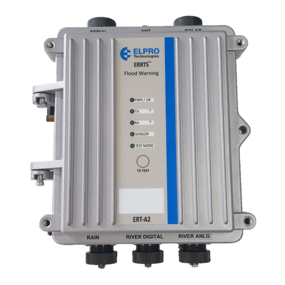
- Page 6 INSTALLATION Enclosure and mounting ELPRO ERT-A2 electronics and battery are enclosed in a rugged IP66 rated cast Aluminium 190mm x 197mm enclosure with an opening/removable door. Sensor and power connection options are: Military specification screw-in connectors (MilSpec) or through cable entry glands with internal industrial push connect wiring terminals.
- Page 7 ELPRO USER MANUAL ERT-A2 Enclosure and mounting If the ERTA2 is to be mounted in a Tree, there is an aluminium accessory holder that allows the Radio and a battery to be housed on a plate that can then be lowered into the tree enclosure similar to the older Legacy cannister.
- Page 8 ELPRO USER MANUAL ERT-A2 INDICATIONS & BUTTONS LED Indications (Front Panel) The LED panel on the front of the ERTA2 will show operational and diagnostic indications. ⚫ PWR/OK Led - Indicates that the unit is powered and running, i.e. processor is operating normally (Green).
- Page 9 ELPRO USER MANUAL ERT-A2 SENSOR INPUT CONNECTIONS The ERTA2 unit can be connected to several different types of external sensor inputs such as discrete on/off, pulsed, 4-20mA analog and SDI-12, allowing a large number of different sensors to be monitored in a single installation.
- Page 10 ELPRO USER MANUAL ERT-A2 SDI-12 Sensor Input Smart sensors can be connected using the SDI-12 interface which can support a single channel with up to 52 sensors/variables. SDI-12 is a three-wire serial sensor bus and allows reading of a number of variables from each sensor on the bus, which can be configured and reported by the ERTA2 unit.
- Page 11 Milspec model which only has the one. It is possible to add second analog to the Milspec model but it would need to be wired directly to the internal terminals. Contact Elpro Support for a procedure on how to do this. USER MANUAL ELPRo-man_ERT-A2_Nov24 EFFECTIVE Nov, 2024...
- Page 12 ELPRO USER MANUAL ERT-A2 Solar The Solar socket allows for the connection of a 5-30W solar panel connection or an external 24V power supply to power or charge the internal Lithium battery or an external fitted Lithium or Lead Acid battery.
- Page 13 (Scada/DCS) using Ethernet, RS-232 or RS-485 serial connectivity. ⚫ RS485: Two wire connection, the default communication to the Elpro 115E-2-A2 Alert Gateway when used as a Receiver Base Station. Generally connection is made via the terminal strip, however it can also be made through the Milspec connector if this is the model you have.
- Page 14 ELPRO USER MANUAL ERT-A2 SYSTEM DESIGN Unit type overview The ERT-A2 unit can be configured through the menu to support any of the three different unit types: ⚫ Field Station: Very low power consumption unit which is in a sleep mode most of the time monitoring its sensor inputs and wakes to send data frames when events occur or on periodic update messages.
- Page 15 ELPRO USER MANUAL ERT-A2 Repeater Station The standard repeater can be configured through the normal configuration menu. There is no special hardware required for repeater mode. The repeater can be used either in ALERT2 or ALERT protocol modes and the protocol can be configured in the communications menu of the unit.
- Page 16 ELPRO USER MANUAL ERT-A2 Summary: ⚫ Base station receiver VHF/UHF radio ⚫ RS-485 A2 data provides a medium distance connection up to 1km (4000ft) to decoder configurable data rate. ⚫ Output communications can be either RS232 or RS485 could support ALERT2 Binary modes ⚫...
- Page 17 ELPRO USER MANUAL ERT-A2 Repeater Station – Multi Frequency or ALERT Migration In systems there can be the need to bring data in from subnetworks that are operating on a different radio frequency. With the ERT-A2 this can be achieved by using a receiver linked to a standard repeater by RS-485.
- Page 18 For initial provisioning of the unit, it is recommended to use the USB port. You will need a USB type A to type B cable to connect your laptop/computer to the ERT-A2 unit. This is commonly used for peripheral devices such as printers/scanners and is available from ELPRO, part number CBLUSB-ATOB.
- Page 19 To access the user menu you will need to use a USB type A to Type B cable. This is usually the type of USB cable you would get with a printer or scanner or see your ELPRO dealer for this accessory.
- Page 20 ELPRO USER MANUAL ERT-A2 Unit Configuration Menu Unit Config menu is where all of the initial provisioning is done and it has the quick start options to allow basic setup of sensor Inputs, i.e. Rain, River and Battery. Unit Configuration...
- Page 21 ELPRO USER MANUAL ERT-A2 ⚫ If analogue, enter the Full range in mm or ft. (Default is 5000) ⚫ Sample Time in minutes (default is 1 minute), Warmup time (default is 5 seconds) ⚫ A sensitivity level, i.e. what threshold will force a transmission. (Default is 10mm or 0.1ft).
- Page 22 ELPRO USER MANUAL ERT-A2 The I/O Setup menu will display options like below. I/O Setup Menu Menu options Description Digital Inputs There are 4 digital inputs, DI1 & DI2 are used for Shaft encoder inputs or can be configured for contact closures or Pulses, DI3 is the primary Pulsed input for Rain, and DI4 an On/Off contact closure.
- Page 23 ELPRO USER MANUAL ERT-A2 Display Scale Allows scale multiplier to be applied to the sensor value that is displayed within the unit. This can be used to scale to engineering units, i.e. a URL height in meters, etc. This value is a float so will allow fractional scaling.
- Page 24 ELPRO USER MANUAL ERT-A2 Scanning for Devices (Automatic) When you select “Scan for Device” or “Manually add” (if you know Address) the ERTA2 will power the sensor and send a query command using the default warmup time. For very slow sensors you may need to adjust this longer to get a response (SDI Sampling Time).
- Page 25 ELPRO USER MANUAL ERT-A2 Manual Commands menu and SDI-12 Diagnostic Menu (same menu) This menu allows to you manually interrogate sensors. Generally the Automatic Scan or the Manual Scan should suffice, however if you are having trouble getting connected to the device you can try some of the these diagnostic commands Note: “IO Setup”...
- Page 26 ELPRO USER MANUAL ERT-A2 Communication Menu The Communication menu is where you setup how the station communicates. The ERT-A2 can have a variety of options, depending on the model. The basic ALERT model is generally a VHF Integrated radio but there is also UHF radio option as well as Cellular modem or Satellite modem.
- Page 27 ELPRO USER MANUAL ERT-A2 Allows the address list to be configured for Pass or Reject IDs. Note: Can only configure 1 x pass list, but Address List Action can have multiple (max 3) reject Lists. Address List Entries Where you enter the ID filter ranges. Can have a maximum of 32 entries within each address list, which is used in conjunction with the List action option above (Pass/Reject).
- Page 28 The receiver RS-485 will output ALERT2 data frames which is usually connected by RS-485 to an ELPRO 115E-2-A2 ALERT2 Decoder-Gateway unit that can be located at a network access point in a server room or IT cabinet.
- Page 29 This generally is used for Remote Cellular connection for configuration and diagnostics via a Cellular modem. Contact Elpro if you need more information on this option. For applications where the 645M-4 is used as a secondary communications channel then its usually best to configure the modem to run permanently powered.
- Page 30 ELPRO USER MANUAL ERT-A2 4G/LTE Primary Communications Operation When the cellular modem is optioned for primary or secondary communications it will be located as a separate module on the door of the ERTA2 unit. Connection between the ERTA2 and the cellular modem is made with a cable providing a switched +12Vdc regulated power supply and RS232 communications.
- Page 31 ELPRO USER MANUAL ERT-A2 Diagnostics menu The ERT-A2 provides a range of diagnostic features to allow quick and successful installation, commissioning and fault finding in the field. Diagnostics Menu Menu option Description Show I/O values Display current external input values for discrete, pulsed and analog inputs. Will force analog loop supply on and display a running sample off all Digital I/O and any configured analog I/O with ID’s (like...
- Page 32 Host firmware is highlighted with a Red rectangle, Bootloader is Yellow and Radio is Cyan. To upgrade any of the firmware version you will need the appropriate files from Elpro Technology, which you can download from the following web link.
- Page 33 From the Diagnostic menu select “Factory Default Erase All” and Acknowledge “yes” Using the button press process described below. Briefly press Reset button (Small hole in top label plate near “Elpro” may require a small screwdriver) Within 2 seconds, press and hold the “Test” button for 5 Seconds.
- Page 34 ELPRO USER MANUAL ERT-A2 the unit has been running and how much data is logged this could take tens of minutes. You are also able to download the file manually, by plugging a USB drive into the unit then select “Upload log to USB”...
- Page 35 ELPRO USER MANUAL ERT-A2 CONTACT HOW TO ORDER Australia Simply send us an email at sales@elprotech.com, contact your local distributor, ELPRO Technologies ELPRO Technologies Inc or phone +61 7 3352 8600 29 Lathe Street 2028 East Ben White Boulevard Virginia QLD 4014...
Need help?
Do you have a question about the ERT-A2 ALERT1 and is the answer not in the manual?
Questions and answers