Table of Contents
Advertisement
Quick Links
Advertisement
Table of Contents

Related Manuals for ELPRO Site Monitoring Kit


Summary of Contents for ELPRO Site Monitoring Kit
- Page 1 Kit User ManUal site Monitoring Kit User Manual we prove it.
-
Page 2: Table Of Contents
Kit Content 1. Introduction 2. Content of the site Monitoring Kit 3. Preparation 1. Positioning of the alarm bracket 2. Positioning of the temperature probe 3. Alarm bracket settings 4. Settings of the alarm behavior 5. Preparation of the refrigerator 4. Installation Installation of the flexible flat cable probe Installation of the thermal damper Installation of the alarm bracket Functional check Mount TemperatureLog 5. Start of operation and monitoring 6. In case of alarm 7. Create PDF report 8. TemperatureLog 9. Display codes / Troubleshooting 1 0. Battery warning and exchange 1 1. After use 12. Connection of an external alarm device... -
Page 3: Introduction
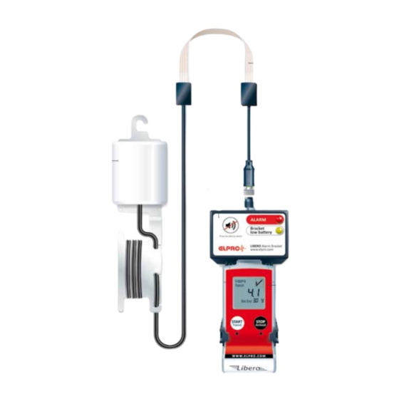
Kit 1. Introduction With the Site Monitoring Kit, ELPRO provides a clever, easy-to-install temperature monitoring system including alerting for remote laboratory cabinets and refrigerators / freezers. The autonomous Site Monitoring Kit offers a reliable 24 / 7 alerting, and observes compliance with the regulations of GMP and FDA 21 CFR Part 11. The Site Monitoring Kit consists of the following hardware: - LIBERO PDF Logger Te1-N that automatically creates a PDF report upon connection to a USB port of a computer. A temperature probe with a thin flexible ribbon cable which adapts perfectly to the gaskets of any laboratory cabinet and enables an installation by the user. - A thermal damper to avoid false alarms - A battery-operated alarm bracket, which provides an audible and visual alarm signal. Optionally, the alarm can be routed to an external alarming system. If required, the LIBERO PDF report can be analyzed and documented in detail by means of the elproVIEWER software. -
Page 4: Content Of The Site Monitoring Kit
Kit 2. Content of the site Monitoring Kit Certificate 1-point calibration certificate for the entire system TemperatureLog Notepad for weekly function check and monthly protocol attachment lIBerO Te1-n Data logger with display and preset alarm conditions Alarm Bracket Full functionality for audible and visual alarming (LED, buzzer, silent button) incl. internal relay for connection to external system Flexible flat cable probe Probe length of 153 cm, 17 cm are flexible ribbon cable Thermal Damper and Cable Manager Delays thermal reaction time (TAU 90) by 35 minutes in order to avoid any false alarms due to frequent door openings (equivalent to the use of a glycol bottle). - Page 5 Kit...
-
Page 6: Preparation
Kit 3. Preparation Before installing the Site Monitoring Kit, the following items should be considered: 1. Positioning of the alarm bracket Option – on the door of the cabinet Option – on the side of the cabinet Make sure that the cable length for the selected positioning is sufficient. Do not place the entire kit within the cabinet! 2. Positioning of the temperature probe There are 3 possibilities to mount the tem- perature probe inside the cabinet. It should be as close as possible to the products to reflect temperatures to which products are exposed. Use the hook to hang it to the middle refrigerator grid shelf Use the adhesive tape to attach it under- neath the middle refrigerator glass shelf Use the adhesive tape to attach it to the side wall... -
Page 7: Alarm Bracket Settings
Kit 3. Alarm bracket settings «silent» period When pressing the «Silent» button, The alarm bracket offers various settings the audio alarm will be suppressed for alarm notification. Before mounting for 30 minutes or 2 hours. the alarm bracket, check the factory settings and if applicable change them «Missing data logger» by means of the DIP switches. The alarm bracket can trigger an alarm if the data logger is missing from the bracket for more than 30 minutes. Buzzer volume The audio alarm has 2 volume levels. Turn buzzer ON / OFF The audio alarm can be turned off or on. switches 1 to 4 The alarm LED is always active. DIP Switch Settings OFF Factory settings 1 Silent period / 30 min 2 h suppression of audio alarm 2 Missing data logger OFF 30 min... -
Page 8: Settings Of The Alarm Behavior
Kit 4. Settings of the alarm behavior 5. Preparation of the refrigerator LIBERO Te1-N is delivered with a standard Important: refrigerator profile, see sample report in In order to reach best possible adhesive kit. It is ready for immediate use. strength, the cabinet should be warmed up to room temperature, cleaned and dried If other settings are required, these can be before any parts are mounted. changed with the liberoCONFIG software. It is downloadable free of charge from www.elpro.com/downloads. -
Page 9: Installation
Kit 4. Installation Once the preparation is completed and all applicable settings have been chosen, the Site Monitoring Kit can be installed. Installation of the flexible flat cable probe Lead the cable between the door and housing of the cabinet. Mount the cable inside of the cabinet. - Clean and dry mounting surface - Remove the paper from the adhesive tape - Fix the adhesive tape by firmly pressing it against the inner refrigerator wall Mount the cable outside of the cabinet according to the chosen position of the alarm bracket. - Carefully close the door - Slightly pull the flexible flat cable to stretch it - Clean and dry mounting surface - Remove the paper from the adhesive tape - Fix the adhesive tape by firmly pressing... -
Page 10: Installation Of The Thermal Damper
Kit Installation of the thermal damper Before the thermal damper is mounted, adjust the cable length and sort the extra cable length with the cable manager: Unwind cable and slide temperature probe as far as possible into the thermal damper Use the first hole to lock the cable and lead it to the back of the cable manager Wind any extra cable around the cable manager Use the second and third hole to hold cable tightly Place the thermal damper at the desired position. Installation of the alarm bracket Align the connector of the flexible flat cable and carefully plug it into the alarm bracket, tighten the silver lock nut. Use the adhesive tape to mount the alarm bracket and fix it by firmly pressing it against the refrigerator door or outside wall. -
Page 11: Functional Check
Kit Functional check Plug LIBERO into the alarm bracket and Logging perform the functional check: Press the Transit «START / Transit» button for 3 seconds. °C Temperature value appears, functional check successfully performed. Bat.End To end the test, press the «STOP / Arrived» Logging button for 3 seconds, the temperature Arrived value disappears. Bat.End If no temperature value appears: - Verify whether LIBERO is fully plugged into the alarm bracket - Verify whether the connection between the cable and the alarm bracket is correct - Display readings are explained in chapter 9 - Repeat test Mount TemperatureLog with the adhesive tape and proceed according to instructions in chapter 8. The installation is now completed. The Site Monitoring Kit is ready for use. -
Page 12: Start Of Operation And Monitoring
Kit 5. Start of operation and monitoring Important: Before loading any material, cool down the cabinet. This may take several hours. In order to start the device, press the «START / Transit» button for 3 seconds. Make sure «Transit» appears in the display; Logging this indicates the alarm conditions are Transit °C active. Make sure that a temperature value appears in the display (current tempera- Bat.End ture). If a start delay has been configured, the display will show «dELY» and the PDF logger will automatically start logging temperature after the set delay time has elapsed. Bat.End If «n.c. » (not connected) is displayed, Logging check installation and consult chapter 9. Transit °C Bat.End... -
Page 13: In Case Of Alarm
Kit 6. In case of alarm Alarming As soon as the configured alarm limits have been exceeded, the LIBERO display changes from OK to ALARM . The alarm bracket is triggered within 10 seconds. − The red LED indicates the alarm (flashing light) − The built-in buzzer gives an audible signal (beep) − The internal relay closes or opens (NO / NC) and notifies an external alarm such as a telephone dialer (if connected). − If the alarm cannot be immediately corrected, press the «Silent» button on the alarm bracket to suppress the audible alarm for 30 minutes (or 2 hours depen- ding on DIP switch position). The red LED remains flashing until the alarm has been reset. Alarm reset and data logger evaluation - Re-establish storage temperature - Generate the PDF report as described - Press «STOP / Arrived» button for in chapter 7 3 seconds to end the current monitoring - Start new monitoring period, period... -
Page 14: Create Pdf Report
Kit 7. Create PDF report In case of alarm or for monthly download, Logging save and archive the PDF report. Perform Arrived °C activities of chapters 6 to 8 as fast as possi- ble in order to avoid any monitoring gaps. - Press «STOP / Arrived» button for 3 seconds to end the current monitoring period. The temperature indication on the LIBERO display disappears. Dis- connect the LIBERO from the alarm Logging Logging Arrived Arrived bracket. If the data logger is not recon- °C nected after 30 minutes, an alarm for «missing data logger» is activated. Bat.End Bat.End − Plug the LIBERO PDF Logger into the USB port of a computer. The display shows «PdF» − Within 20 seconds, the PDF report will The LIBERO PDF report has all recorded automatically generate (file may show in data embedded into the PDF file. Windows Explorer) The recorded data can be analyzed further with elproVIEWER. In case the PDF report does not appear... - Page 15 Kit PDF report Alarm Indicator: Alarm statistics: OK or ALARM for the last monitoring period Additional information: Logging results: configurable by means of free the shown temperature curve and liberoCONFIG software statistical data refer to the last Device information: monitoring period only, i.e. since as e.g. data logger ID no, reported time the last restart base, remaining battery life, the chosen logging interval defines the number of days in memory...
-
Page 16: Temperaturelog
Kit 8. TemperatureLog The self-adhesive notepad is mounted Temperature should be checked frequently, directly onto the refrigerator / freezer. but at least once every week. We recom- It can be used as a weekly check signoff, mend documenting the weekly checks with serves as a guideline in case of an alarm, date and initials in the TemperatureLog. and can be attached to the PDF report as monthly protocol. Fill in TemperatureLog: FILLED EXAMPLE - Logger ID - Expiry date of the calibration certificate - Company - Location - ID number / name of the cabinet - Shown temperature with date and initials... -
Page 17: Display Codes / Troubleshooting
Kit 9. Display codes / Troubleshooting Code Meaning Recovery Action LIBERO is in start mode Press «START / Transit» button for and not yet activated. 3 seconds to start monitoring and No temperature logging activate the alarm conditions. takes place! Bat.End Data logger is in Normal case, no measures necessary. Logging TRANSIT mode. Transit °C Temperature monitoring takes place. Bat.End Data logger is in Temperature is or has been outside Logging ALARM state. of the defined alarm ranges. Transit °C Temperature monitoring Resolve failure. Establish PDF report. takes place. Bat.End PDF report After creating PDF report, reconnect LIBERO Logging is being created. to the alarm bracket. Press «START / Tran- Arrived °C... -
Page 18: 0. Battery Warning And Exchange
Kit 10. Battery warning and exchange The alarm bracket is self-sustaining and powered by internal batteries. The power is not supplied by the connected LIBERO PDF Logger. We recommend changing the batteries once every year or at the latest when the yellow «Bracket low battery» LED is lit. To exchange the batteries open the alarm bracket cover. Carefully remove the used batteries and exchange them with 3 new Alkaline AAA 1.5 V batteries. 11. After use - Remove batteries from the alarm bracket – see above – and dispose them of accor- ding to local procedures - Data logger, temperature probe and alarm bracket are disposed of as electronic waste... -
Page 19: Connection Of An External Alarm Device
Kit 12. Connection of an external alarm device The alarm bracket has a built in alarm relay, which can trigger an external device (GSM interface or automatic telephone dialer) Relay connection The relay contains a dry contact 3-way switch. As soon as the red LED is flashing, the relay contact changes to the «Alarm» position. The external alarm has to be connected to the internal terminals; it cannot be attached to the probe connector. Maximum switching load: 42 VDC or VAC; 500 mA No alarm Alarm... - Page 20 ELPRO-BUCHS AG | Langäulistrasse 62 9470 Buchs SG | Switzerland T +41 81 750 03 11 | swiss@elpro.com For local representations see: www.elpro.com/contact www.elpro.com Swiss Engineering...
Need help?
Do you have a question about the Site Monitoring Kit and is the answer not in the manual?
Questions and answers