Advertisement
Quick Links
12/22
Application
Electrification of numerous industries is
prevalent. This is especially true for the
automotive industry. Voltage levels of next
generation powertrains or batteries in electric
carsand trucks are increasing. Currently, 800-
1200 V is made standard to achieve higher
efficiency and faster charging time. This poses
challenges to the safety of workers and
equipment during manufacturing and testing of
high voltage powertrain components using a
failsafe voltage threshold (for example 50
VDC).
Due
to
the
configuration, the HVT 300 series is suitable
for
numerous
industries
electrification components.
Mütec Instruments – Your safe choice
Bei den Kämpen 26
D-21220 Seevetal-Ramelsloh
707
flexible
software
and
various
Tel.: +49 4185/8083-0
Fax: +49 4185/8083-80
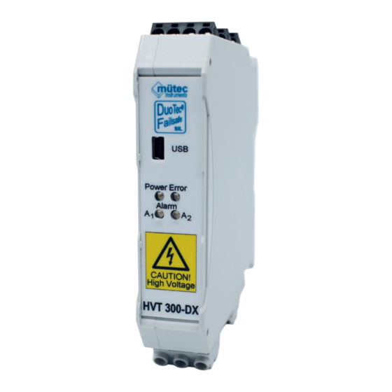
HVT 300-DX
High Voltage Monitor
For up to 1.000 V
Features
-
SIL 2 according to IEC/EN 61508
-
1000V input range
-
Device
type
B
IEC/EN 61508
-
Safety function via mA-output and
relays ¾
-
Limit alarm monitoring via relays ½
-
Redundant supply via terminals
and DIN rail connector
-
USB 2.0 interface
-
RS485 / Modbus RTU interface
-
failure
display
NAMUR NE 43
-
LED status: Power, Error, Alarm
Mail:
muetec@muetec.de
Web:
www.muetec.de
Failsafe
according
to
according
to
1
Advertisement

Related Manuals for Mutec HVT 300-DX


Summary of Contents for Mutec HVT 300-DX
- Page 1 12/22 HVT 300-DX Failsafe High Voltage Monitor For up to 1.000 V Features Application SIL 2 according to IEC/EN 61508 Electrification of numerous industries is 1000V input range prevalent. This is especially true for the Device type according automotive industry. Voltage levels of next...
- Page 2 12/22 Manual HVT300-SIL-DX WINSMART-Support from version 4.0 MODBUS-RTU Communication Doc-Nr.: Revision: Issue date: 12/2022 Manufacturer: Mütec Instruments GmbH Bei den Kämpen 26 21220 Seevetal Deutschland Tel.: +49 (0) 4185 8083-0 Fax: +49 (0) 4185 808380 E-Mail: info@muetec.de Internet: www.muetec.de Licence-, trademark and copyright notes Modbus™...
- Page 3 12/22 Content Safety instructions and installation ................4 Safety Instruction Classifiction .................. 4 General Instructions ....................6 Technical Data ......................10 Certificate ............................. 10 Measurement Input ........................10 Analog Output ..........................10 Limit Alarm Relay Outputs ......................10 SIL2 Diagnostic Alarm Relay Outputs ..................11 LEDs ............................
- Page 4 12/22 Safety instructions and installation Note: Installation, operation and maintenance may only be carried out by qualified specialst personnel. When installing and operating the device, the applicable safety guidelines (including the national safety guidelines), accident prevention regulations and general technical regulations must be observed.
- Page 5 12/22 CAUTION without a triangular warning sign means that material damage may occur if the appropriate precautionary measures are not taken. ATTENTION means that an undesired result or state may ensue if the corresponding instruction is not followed. NOTE denotes important information about the product, handling of the product or the respective part of the documentation, is aimed at drawing special attention to the latter and should be complied with.
- Page 6 12/22 General Instructions This device left the plant in flawless condition in terms of its safety features. To preserve this condition and ensure safe operation of the device, the user has to observe the instructions and warning notes indicated in this operating manual. For the sake of clarity the manual does not contain complete detailed information on all product types and can therefore not take into account every conceivable case with respect to installation, operation and maintenance.
- Page 7 12/22 QUALIFIED PERSONNEL Qualified personnel are persons who, due to their training, experience and instruction as well as their knowledge of relevant standards, regulations, accident prevention regulations and operating conditions, have been authorized by the person responsible for the safety of the system to carry out the necessary planning and activities and thereby recognize and recognize possible dangers can avoid.
- Page 8 12/22 SAFETY INSTRUCTIONS The safety regulations of electrical engineering and the trade association must be observed and adhered to. Failure to observe the safety regulations can result in death, severe physical injury or extensive property damage. DIRECT / INDIRECT TOUCHING Protection against direct and indirect contact in accordance with VDE 0100 Part 410 must be guaranteed for all components connected to the system.
- Page 9 12/22 ELECTROSTATIC DISCHARGE Potentially electrostatic components may be destroyed by voltage that is far below the limits of human perception. Such voltage occurs even when you touch a component or electrical connections of a component and are not electrostatically discharged. The damage that occurs to a component because of overvoltage usually cannot be detected immediately and does not become noticeable until after a longer operating period.
- Page 10 12/22 Technical Data Certificate Functional Safety SIL2 according to IEC 61508 Measurement Input A parameterizable 1st order filter of (0.1 - 99.9) s is available for the measurement inputs. To improve the EMC, a hinged ferrite can be placed on the cable for the measurement input (Mütec Instruments order no.: E30724) NOTE: The HVT 300 has a different Pin-In compared to the HVT 400.
- Page 11 12/22 SIL2 Diagnostic Alarm Relay Outputs (T-7+ T-8 and T-9 + T-10) Relays REL3/REL4 Type: Normally open Funtion: Safety function activated Contact: Closed in good condition Switching power: max. 62,5 VA / max. 30 W Switching voltage: max. 125 V AC / 110 V DC Switching current: max.
- Page 12 12/22 Temperature coefficient Maximum: < 0,01 %/K Typical: < 0,005 %/K Galvanic Isolation 3 port isolation: Input / output / supply Input / Output: 4,3 kV AC test voltage Input / Supply: 4,3 kV AC test voltage Overvoltage category: CAT II: 1000 V AC/DC Pollution level: 1 according to IEC 61010-1 Electrical Connection...
- Page 13 12/22 4.12 Installation TBUS-Connection TBUS-Connector with DIN-rail Mounting and dismounting of a DIN-rail housing Figure 1 - DIN-rail housing and mounting Technical Data: 5-pole connector in 3.81mm pitch 8A maximum contact load Gold plating ensures high contact quality. Designed for mounting to NS 35/7.5 or NS 35/15 DIN rails Important note: The device may only b Attached to or removed from the TBUS-Connection when power is switched off! Attach the housing to a 35 mm DIN-rail according to EN 60715.
- Page 14 12/22 4.14 Housing Dimensions Figure 2: Housing Dimensions 4.15 Block diagram Figure 3: Block diagram and galvanic isolations Mütec Instruments – Your safe choice Bei den Kämpen 26 Tel.: +49 4185/8083-0 Mail: muetec@muetec.de D-21220 Seevetal-Ramelsloh Fax: +49 4185/8083-80 Web: www.muetec.de...
- Page 15 12/22 4.16 Nameplate Figure 4: Name plate Variants of Input Connections mV Measurement in 2-wire connection Figure 5: 2-wire input configuration The absolute value measurement with only one measuring input is a possibility of interconnection with the signal source and the transmitter, if the terminals T-18 and T-19 are bridged HAZARD A line break in the measuring circuit would be detected by the...
- Page 16 12/22 mV Measurement in 4-wire connection Figure 6: 4-wire input configuration Only the 4-Lt. circuit enables the comparison of both mV signals at the measuring inputs of the mV transmitter. An increased lead resistance and associated voltage drop on one lead results in a difference between the two mV signals.
- Page 17 12/22 Loop resistance calculation for the mA Output Analog output (AO) data for constant current: max. 22 mA at a load ≤ 500 Ω. The maximum load for the analog output is the sum of the forward and return lines and the input resistance (shunt) of the following module: = 2x R ≤...
- Page 18 12/22 Safety Safety Function In case parameters are exceeding the accuracy settings the analogue output current of the device switches to the safe state. The diagnostic relays (REL3 and REL4) indicate the internal status of the diagnostics. The safety function consists of the logical combination of limit relays (REL1/REL2) or analog output and the status of the diagnostic relays (REL3/REL4).
- Page 19 12/22 Safety-Relevant Features Properties FMEDA Category SIL 2 Device type Type B 95 % 89 % Safe failure rate 331 FIT Safe detected failure rate 0 FIT Safe undetected failure rate 331 FIT Dangerous failure rate 362 FIT Dangerous detected failure rate 325 FIT Dangerous undetected failure rate 37 FIT...
- Page 20 The operating mode with a low request rate is used as a basis. The proportion of the HVT300- SIL-DX at the PFDAVG value of the entire safety chain should not exceed 30%. Signal Source HVT 300-DX Signal Processing (PLC) Conditions: •...
- Page 21 12/22 If you have any questions or concerns, please do not hesitate to contact us! Mütec Instruments GmbH Bei den Kämpen 26 D-21220 Seevetal-Ramelsloh Germany Tel.: + 49 (0)4185-8083-0 Fax: + 49 (0)4185-8083-80 Mail: muetec@muetec.de Web: www.muetec-instruments.de Follow us on Linkedin! www.linkedin.com/company/muetec Mütec Instruments –...
Need help?
Do you have a question about the HVT 300-DX and is the answer not in the manual?
Questions and answers