Table of Contents
Advertisement
Quick Links
06/24
Continuous inline moisture measurement
Application
Moisture in solids is an important parameter that in-
fluences the quality of a product and the economic
efficiency of production. Nevertheless, in many
companies, product moisture is only determined in
the laboratory. These random sample measure-
ments are time-consuming and the results are only
available with a delay.
The HUMY 301 inline moisture measurement sys-
tem is the better alternative. Its real-time measure-
ment enables an immediate response to moisture
changes in the process. The measurement results
can be used to control a dryer or automatic humidi-
fication or to continuously monitor the process.
At the Kämpen 26
D-21220 Seevetal-Ramelsloh
790
HUMY 301
of bulk goods
Mütec Instruments - Your safe choice
Phone: +49 4185/8083-0
Fax: +49 4185/8083-80
Industries
Aluminum
Bakeries
Building materials
Chemical industry
Fertilizer
Power generation
Glass production
Wood industry
Mills
Food industry
Surface cleaning
Paper and pulp
Pharmaceuticals
Steel industry
Cement industry
etc.
Mail:
muetec@muetec.de
Web:
www.muetec.de
Advertisement
Table of Contents

Subscribe to Our Youtube Channel
Related Manuals for Mutec HUMY 301


Summary of Contents for Mutec HUMY 301
- Page 1 Glass production available with a delay. Wood industry The HUMY 301 inline moisture measurement sys- Mills tem is the better alternative. Its real-time measure- Food industry ment enables an immediate response to moisture Surface cleaning changes in the process.
- Page 2 06/24 Manual Doc. no: Revision: Date of issue: 27.06.2024 Mütec Instruments GmbH Bei den Kämpen 26 21220 Seevetal Germany Phone: +49 (0) 4185 8083-0 Fax: +49 (0) 4185 808380 E-mail: info@muetec.de Internet :www.muetec.de License, trademark and copyright notices Copyright © Mütec Instruments GmbH All rights reserved This document is protected by copyright.
-
Page 3: Table Of Contents
13.1 The start screen........................25 13.2 Selecting the language ......................25 13.3 Connect Humy 301 transmitter to PC ..................26 13.4 Selecting and activating the Humy 301 transmitter ..............27 13.5 Deactivate transmitter ......................28 13.6 Remove device ........................28 Mütec Instruments - Your safe choice... - Page 4 06/24 Parameterization of the measuring system............. 29 14.1 Parameterization in standard mode ..................29 14.1.1 Transmitter settings ......................29 14.1.2 Products/Calibration ......................30 14.1.3 Online view .......................... 31 14.1.4 Offline analysis ........................35 14.2 Parameterization in expert mode .................... 37 14.2.1Settings of the transmitter (additional functions) ..............
-
Page 5: Safety Instructions And Installation
06/24 Safety instructions and installation Note: Installation, operation and maintenance may only be carried out by qualified personnel. The applicable safety guidelines (including national safety guidelines), accident prevention regulations and general technical rules must be observed when in- stalling and operating the appliance. Note: The device's circuits must not be accessed. - Page 6 06/24 CAUTION without a triangular warning sign means that material damage may occur if the appropriate precautions are not taken. ATTENTION means that an undesired result or an undesired state can occur if the corresponding instruction is not followed. NOTES indicates important information about the product, the handling of the product or the respective part of the documentation, is intended to draw particular attention to it and must be observed .
-
Page 7: General Instructions
All modifications to the device are the responsibility of the user, unless expressly stated otherwise in the operating instructions . VALIDITY The data sheet is only valid for the HUMY 301 described and the hardware/firmware version specified in the technical data Mütec Instruments - Your safe choice At the Kämpen 26... - Page 8 06/24 QUALIFIED PERSONNEL Qualified personnel are persons who, due to their training, experience and instruction as well as their knowledge of relevant standards, regulations, accident prevention reg- ulations and operating conditions, have been authorized by the person responsible for the safety of the system to carry out the necessary planning and activities and are able to recognize and avoid potential hazards.
- Page 9 06/24 SWAPPING AND REVERSING THE CONNECTIONS Take measures to avoid mix-ups, reverse polarity or tampering with the connections DAMAGED DEVICE If a fault occurs, the device may be damaged. Correct and safe operation is then no longer guaranteed and the device should therefore be replaced. Only the manufacturer or a person authorized by the manufacturer may open the housing and repair the device.
-
Page 10: Technical Data
06/24 Technical data Transmitter General data Housing Material: Protection class: IP20 Flammability class: VO according to UL Dimensions (WxLxH): 22.5 mm x 114.5 mm x 99 mm without clamps Weight: 250 g Design: Terminal enclosure for mounting rail installation Mounting/installation posi- tion: Limit values Permissible temperature:... - Page 11 06/24 Energy supply Supply Voltage: 24 VDC (18..30V) Power consumption: max. 2.0 W Analog output: Output value: up to 22 mA / 11 V Accuracy: 40 uA / 20 mV Load (mA): up to 500 Ohm Burden (V): up to 50 kOhm Rise time: max.
-
Page 12: Sensor
06/24 Data interfaces USB interface: Technology: USB 2.0, Mini-USB Speed: up to 115200 baud Supply: galvanically isolated area: from PC Separation: galvanically isolated RS485 interface: Speed: up to 115200 baud Termination: Software-controlled Biasing: None Supply: galvanically isolated area: from device Separation: galvanically isolated Sensor... - Page 13 06/24 Data connection Interface: RS485 Termination: 470R Biasing: 1k0 between 0 and 5 V Separation: galvanically isolated Baud rate 19200 bps Device address: Material FMS410K: FMS410C: Ceramic (with POM inner cup) FMS410T: PTFE FMS410S: Ceramic (with PTFE inner cup; recommended for CIP) Limit values Compressive strength: max.
-
Page 14: Dimensions
06/24 Dimensions Transmitter Sensor Mütec Instruments - Your safe choice At the Kämpen 26 Phone: +49 4185/8083-0 Mail: muetec@muetec.de D-21220 Seevetal-Ramelsloh Fax: +49 4185/8083-80 Web: www.muetec.de... -
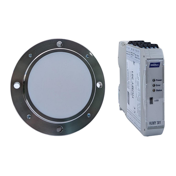
Page 15: Intended Use
06/24 Intended Use The moisture measuring system consists of the HUMY 301 control and evaluation unit in a top- hat rail housing and the FMS 410 moisture sensor. The inline measuring system for process monitoring guarantees trouble-free measurement of the internal product moisture of solids and emulsions. -
Page 16: Setup Oft He Sensor
06/24 Setup of the Sensor Built into a solid cylindrical stainless steel housing, the probe is largely insensitive to external influences. A special internal encapsulation protects the entire electronics from the ingress of moisture and increases resistance to alkalis, acids and solvents. The electrical connection is made via a fixed cable connection in the probe and guarantees IP67 tightness thanks to the high-quality PG screw connection. -
Page 17: Assembly
06/24 Assembly Mounting of transmitter The ME-MAX housing can be combined with a 5-pole TBUS connector/ DIN rail connector. The RS485 interface and the supply voltage can be conveniently wired through via the TBUS con- nector snapped into the top-hat rail. The TBUS connection is set up automatically in the grid of the devices involved. -
Page 18: Mounting Of Sensor
06/24 Mounting of sensor The HUMY 301 is designed for continuous moisture measurement in the production flow. The prerequisite for correct moisture measurement in bulk materials is always the correct choice of installation location for the moisture probe. With bulk material chutes or conveyor belts, care must also be taken to ensure that the measured material is guided over the probe with as uniform a layer height as possible. -
Page 19: Conveyor Belt
06/24 9.2.3 Conveyor belt Installation on a conveyor belt 9.2.4 Trough chain conveyor Installation on a trough chain conveyor 9.2.5 Slide Installation on a slide Mütec Instruments - Your safe choice At the Kämpen 26 Phone: +49 4185/8083-0 Mail: muetec@muetec.de D-21220 Seevetal-Ramelsloh Fax: +49 4185/8083-80 Web:... -
Page 20: Free-Fall Tube
06/24 9.2.6 Free-fall tube Installation in a free-fall application: 9.2.7 Installation with a separating layer Indirect installation of the HUMY probe is necessary if the wall thickness is 10 mm or more or if the wall is curved. In such cases, the use of a weld-on flange is recommended. 9.2.6 Mounting with a protective cap The measuring window must be in direct contact with the material to be measured. -
Page 21: Outdoor Installation
06/24 The recommended arrangement for chain conveyors or for measuring media with a temperature of over 80°C up to a maximum of 120°C is the use of a separating layer of 5 to 15 mm. The permissible thickness depends on the material to be measured and the residual water content. The measuring surface of the moisture sensor must always have mechanical contact with the separating layer. -
Page 22: Electrical Connection
06/24 10 Electrical connection 10.1 Transmitter terminal assignment Terminal 1 mA out (+) Terminal 13 DI 1 (+) Terminal 2 mA out (-) Terminal 14 DI 1 (-) Terminal 3 Supply (+) Terminal 15 DI 2 (+) Terminal 4 Supply (-) Terminal 16 DI 2 (-) Terminal 5... -
Page 23: Installing The Cables
06/24 The cable shield is connected to the earthing contact in the probe. If the cable shield is also earthed at the other end of the cable and there is a significant po- tential difference between the two earthing points, a considerable equalizing current flow across the cable shield can be the result. -
Page 24: Introduction To The Huconfig Software
13 Installing and configuring the software The setup wizard for installing the software on the laptop/PC is started with the file "Humy 301 Configuration Setup.exe". After selecting the installation directory, it is possible to install the driver for the USB connection automatically (only necessary if there was no connection to a Mütec transmitter or other device with a USB interface before):... -
Page 25: The Start Screen
06/24 13.1 The start screen After starting the software, the connected measuring systems (left) and the configuration menu (right) with the most recently edited configuration folder are displayed. Current measured values of the se- Menu bar lected measuring device Shortcuts Connected measuring devices Configuration tabs 13.2... -
Page 26: Connect Humy 301 Transmitter To Pc
06/24 13.3 Connect Humy 301 transmitter to PC A physical connection to the laptop/PC must be available to configure the transmitter. If the transmitter is successfully connected, a virtual COM port is created in the Windows Device Man- ager. If this is not the case, please install the supplied USB driver manually. You will find the driver in the selected installation directory in the DRIVER folder. -
Page 27: Selecting And Activating The Humy 301 Transmitter
If the connection to the transmitter is successful, a green tick appears next to the device. displayed. 13.4 Selecting and activating the Humy 301 transmitter For parameterization and calibration, the parameters are loaded by clicking on the device. The current measured values (raw value, scaled humidity value, sensor temperature) and the status of the transmitter are displayed in the status field. -
Page 28: Deactivate Transmitter
06/24 13.5 Deactivate transmitter To reduce the data rate when several transmitters are connected, the connection can be dis- connected via the menu item 'Device management' ► 'Device active' ► "Name of device" or by right-clicking on the device: A deactivated device is symbolized with a red circle and data recording for the device is inter- rupted: 13.6 Remove device... -
Page 29: Parameterization Of The Measuring System
06/24 14 Parameterization of the measuring system 14.1 Parameterization in standard mode The basic settings of the moisture measurement system can be made in standard mode. Standard mode is set via the 'Access mode' ► 'User' menu. Parameterization and calibration are carried out via the configuration tabs. -
Page 30: Products/Calibration
06/24 14.1.2 Products/Calibration Menu for configuring the product-specific parameters and for calibrating the products. Up to 24 different products can be stored. Select product: Select the product whose parameters or configuration are to be changed. If the "Current product" checkbox is set, all changes relate to the product currently in use, i.e. -
Page 31: Online View
06/24 14.1.3 Online view In the online display, up to 8 measured values from different Humy301 transmitters can be dis- played simultaneously. The following measured values can be selected for the online display: Scaled value: Moisture value of the selected product (calculated according to the stored calibration curve) Raw value: Unfiltered raw value of the measuring probe in digits... - Page 32 06/24 Grid used: Selection of the measured value to which the grid is related Autoscaling °C: Automatic scaling of the temperature axis to the optimum display range. The scaling of the Y-axis changes after pressing the but- Autoscaling %: Automatic scaling of the Y-axis for the moisture values to the op- timum display range Autoscaling raw: Automatic scaling of the Y-axis for the raw values to the optimum...
- Page 33 06/24 Description: Description of the measured value (freely configurable) Source device: Selection of the moisture measuring system (max. 8 measuring systems can be managed) Measurement: Selection of the measured value for the online display (see above) Median/Pt1/screw filter: Setting the measured value filters for the online display (only if 'Raw value' is selected).
- Page 34 06/24 Scaling of the measured values: Basic settings for manual scaling of the measured values and the time axis can be made in the 'Scaling' ► 'Scaling X/Y axis' menu. By activating the 'Use default scaling' option, the settings for the diagram are saved. If a diagram section is changed using the zoom function, the saved scaling setting can be restored in the 'Diagram' menu ►...
-
Page 35: Offline Analysis
06/24 Export measured values The displayed measured values can be exported as a csv file or as a bitmap for documentation purposes. In the menu 'Export' ► 'Export displayed data (.csv)’ or via the Export as csv file: button Export as bitmap: In the menu 'Save diagram as bitmap' or via the button Settings for csv-export: Choose decimal point (. - Page 36 06/24 The following window appears: Description: Description of the measured value (freely configurable) Log file directory: Selection of a log file for analyzing the measured values. The file name contains the device name, the serial number of the transmit- date (yyyymmdd).
-
Page 37: Parameterization In Expert Mode
06/24 The directory for the log file is defined in the configuration of the device (see menu 'Device management' ► 'Edit setting' ► "Name of the device"). The operation and functions of the graphical user interface are identical to those of the online view. -
Page 38: Digital Inputs
06/24 14.2.2 Digital inputs Configuration of the digital inputs. The Humy301 transmitter is equipped with 4 digital inputs with different functions. No function: The digital input is deactivated Freeze measured value: The measured value is frozen when a rising edge is detected (direction of the signal can be set via "Direction") and does not change. -
Page 39: Batch Control
06/24 14.2.3 Batch control In certain processes, the product is conveyed in batches. The product moisture can then only be measured over a short period of time. To ensure that the measured value is not influenced by unstable process conditions at the beginning and end of the batch (e.g. different pouring height or bulk density, sensor not covered with product), the product inlet and outlet can be blanked out when using a trigger sensor (e.g. -
Page 40: Outputs
06/24 14.2.3 Outputs The alarm outputs and the analog output for data transmission to a PLC are configured in the "Outputs" menu. A relay and a transistor output are available for outputting the alarm values. Alarm values can also be output as an analog value. The output value in the event of an alarm is freely configu- rable. -
Page 41: Products/Calibration (Additional Functions)
06/24 Output mode: Effective direction of the alarm output Delay: Switching delay time of the output value Activation matrix: Selection of the available alarm value (moisture value min/max, over/un- der temperature of the sensor, sensor error) Analog output: Configuration of the analog output Output mode: Selection of current (4...20mA) or voltage output (0...10V) Output value:... -
Page 42: Read/Write Parameters
06/24 14.3 Read/write parameters Changes to parameters or calibration curves are initially saved temporarily and must be written to the transmitter memory after each change in the 'Device settings' ► 'Write configuration' menu or by clicking on the symbol must be written: After changing parameters and switching to another menu or exiting the program, you will be prompted to save the parameters. - Page 43 06/24 An existing configuration is loaded in the 'File' menu ► 'Load configuration' or with the folder symbol loaded. Mütec Instruments - Your safe choice At the Kämpen 26 Phone: +49 4185/8083-0 Mail: muetec@muetec.de D-21220 Seevetal-Ramelsloh Fax: +49 4185/8083-80 Web: www.muetec.de...
-
Page 44: Calibration
06/24 15 Calibration A good and precise calibration is essential to achieve a high level of measurement accuracy. The number of calibration points must be determined first. In most cases, 2 calibration points are sufficient, in which case linear behavior is assumed. A maximum of 5 calibration points can be selected. -
Page 45: Number Of Calibration Points
06/24 Example: The expected moisture range is between 10 and 15%. Recommended setting for scaling the analog output: 5% (range start 4mA) - 20% (range end 20mA). 15.2 Number of calibration points A calibration curve can be created with a minimum of 2 to a maximum of 5 calibration points, depending on the accuracy requirement. -
Page 46: Determining The Optimum Filter Value
06/24 15.4 Determining the optimum filter value The software offers various filter algorithms for smoothing the digital output signal. A combina- tion of median filter for eliminating outliers and Pt1 average filter for smoothing the signal is recommended. The filter values can be changed in the online view and the effect on the signal can be tested directly. - Page 47 06/24 Raw signal with activated median filter over 7 measured values: Raw signal with activated median filter over 7 measured values and mean value filter PT1 (filter length 5s): Mütec Instruments - Your safe choice At the Kämpen 26 Phone: +49 4185/8083-0 Mail: muetec@muetec.de D-21220 Seevetal-Ramelsloh...
-
Page 48: Graphical Determination Of A Calibration Point
06/24 A large time constant of the mean value filter leads to optimum smoothing of the signal, but abruptly changing signal curves are registered with a time offset. A combination of median fil- ter and subsequent smoothing using a PT1 mean value filter is therefore recommended. For static measurements, a median filter value of 3 measured values and a mean value of 2s is usually sufficient to smooth out the noise of the digital value. -
Page 49: Offline Calibration
06/24 15.6 Offline calibration Similar to the graphical determination of a calibration point, calibration can also be carried out using historical data. This means that a laboratory sample can be taken and analyzed at any time during the process, which is then later assigned to a historical raw value. Example: A laboratory sample was analyzed on 15.05.2024 at 15:05. -
Page 50: Troubleshooting
06/24 16 Troubleshooting The following table contains a list of possible causes of errors when using the moisture meas- urement system. If the error has not been rectified, please contact Mütec Instruments technical support: 16.1 Software or hardware-related error causes Error image Possible cause Measure... -
Page 51: Process-Related Causes Of Errors
06/24 Analog output remains at max. Current humidity value is greater Check the scaling of the current value than end of range in the product output in the "Products/Calibra- menu tion" menu Measured value is not displayed Analog output defective Measure analog output in the PLC PLC analog input card... - Page 52 06/24 If you have any questions or comments, please do not hesitate to contact us! Mütec Instruments GmbH At the Kämpen 26 D-21220 Seevetal-Ramelsloh Germany Tel.: + 49 (0)4185-8083-0 Fax: + 49 (0)4185-8083-80 Mail:muetec@muetec.de Web: www.muetec-instruments.de Follow us on Linkedin! www.linkedin.com/company/muetec Mütec Instruments - Your safe choice At the Kämpen 26...
Need help?
Do you have a question about the HUMY 301 and is the answer not in the manual?
Questions and answers