Table of Contents
Advertisement
Quick Links
Mütec Instruments GmbH
Bei den Kämpen 26
D-21220 Seevetal-Ramelsloh
Operating Manual
MSBA00049
Operating Manual FS750E
Dust monitoring
with analog output
for the detection of
filter malfunctions
Tel.: +49 (0) 4185-80 83-0
Fax: +49 (0) 4185-80 83-80
Date:
21.03.2019
Rev.:
05
Page
1 of 14
E-Mail:
muetec@muetec.de
Web:
www.muetec.de
Advertisement
Table of Contents

Subscribe to Our Youtube Channel
Related Manuals for Mutec FS750E


Summary of Contents for Mutec FS750E
- Page 1 Date: 21.03.2019 Operating Manual Rev.: MSBA00049 Page 1 of 14 Operating Manual FS750E Dust monitoring with analog output for the detection of filter malfunctions Mütec Instruments GmbH Tel.: +49 (0) 4185-80 83-0 E-Mail: muetec@muetec.de Bei den Kämpen 26 Fax: +49 (0) 4185-80 83-80 Web: www.muetec.de...
- Page 2 Date: 21.03.2019 Operating Manual Rev.: MSBA00049 Page 2 of 14 Operating Manual FS750E Operating Manual for FS750E No.: MSBA00049-50 Issue date: 03/2019 Manufacturer: Mütec Instruments GmbH Bei den Kämpen 26 21220 Seevetal Deutschland Tel.: +49 (0) 4185 8083-0 Fax: +49 (0) 4185 8083-80 E-Mail: info@muetec.de...
-
Page 3: Table Of Contents
21.03.2019 Operating Manual Rev.: MSBA00049 Page 3 of 14 Operating Manual FS750E Table of Contents Classification of the safety instructions ................4 General Instructions ....................... 5 Introduction ........................6 System Design ....................... 7 General information on construction and operation ............7 Mounting Instructions ..................... -
Page 4: Classification Of The Safety Instructions
MSBA00049 Page 4 of 14 Operating Manual FS750E 1 Classification of the safety instructions This manual contains instructions that you have to observe for your personal safety as well as to avoid material damage. These instructions are highlighted using a triangular warning sign and shown as follows, depending on the degree of risk. -
Page 5: General Instructions
MSBA00049 Page 5 of 14 Operating Manual FS750E 2 General Instructions This device left the plant in flawless condition in terms of its safety features. To preserve this condition and ensure safe operation of the device, the user has to observe the instructions and warning notes indicated in this operating manual. -
Page 6: Introduction
6 of 14 Operating Manual FS750E 3 Introduction The dust indicator FS750E is intended for the use at the clean air side to detect dust behind a filter. In this way, filter cracks, fractures or assembly errors are reported automatically and reliably. -
Page 7: System Design
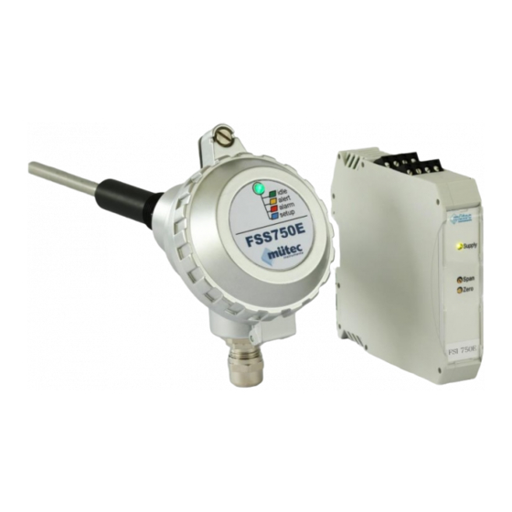
Page 7 of 14 Operating Manual FS750E 4 System Design The system FS750E consists of a dust monitor and a DIN-rail transmitter. The sensor is connected to the transmitter via a 4-wire cable. The measured value of the particle load is then transferred to the transmitter and is available as 4-20mA signal at the analog output. -
Page 8: Mounting Instructions
Operating Manual FS750E 6 Mounting Instructions 6.1 Selection of the mounting position The inlet and outflow zone for FS750E should not be less than 3 times the nominal diameter. After fixing the threaded sleeve in a 90° angle to the tube axis, the mounted weld must close the gap between the sleeve and the pipe wall reliably. -
Page 9: Transmitter Mounting
21.03.2019 Operating Manual Rev.: MSBA00049 Page 9 of 14 Operating Manual FS750E 6.3 Transmitter Mounting Mount the transmitter on a 35 mm DIN rail according to EN 60715. Install the module in a suitable housing to meet the requirements for the protection class. -
Page 10: Electrical Connection
4-20mA range. 8.2 Calibration The FS750E is pre-calibrated by the manufacturer. The entire measuring range is mapped to the output range 4-20mA. There are two adjustment options for an individual customization of the analog output range. -
Page 11: Operation
Operating Manual Rev.: MSBA00049 Page 11 of 14 Operating Manual FS750E 1. Sensor Adjustment The amplification factor of the sensor can be adjusted by the gain switch (see figure 6). Figure 6: View of sensor board 2. Transmitter Adjustment The analog output range of the DIN-rail transmitter can be adjusted with the potentiometers ZERO and SPAN. -
Page 12: Technical Data
Date: 21.03.2019 Operating Manual Rev.: MSBA00049 Page 12 of 14 Operating Manual FS750E 9 Technical Data 9.1 Flow-Sensor FSS750E Housing material: Aluminum Material sensor rod: V2A / V4A (option) Isolator: Protection class: IP65 Weight: 700g Tightening torque - mounting: 40Nm Storage temperature: -20°C to +70°C (not condensing) -
Page 13: Transmitter Fsi750E
Date: 21.03.2019 Operating Manual Rev.: MSBA00049 Page 13 of 14 Operating Manual FS750E 9.2 Transmitter FSI750E Analog output 4 … 20 mA Constant current: Output value: max. 20.5 mA max. 750 Ω Load: ≤ 0,02 % Load influence: Damping: filter 1st order, fixed... -
Page 14: Service And Maintenance
Rev.: MSBA00049 Page 14 of 14 Operating Manual FS750E 10 Service and maintenance When using the measuring device at abrasive materials, the product stream exposed areas must be regularly checked for their dimensions. The loss of material must not be more than 1mm.
Need help?
Do you have a question about the FS750E and is the answer not in the manual?
Questions and answers