Advertisement
Quick Links
Z 4-03
No.
907900B
) 0330
0 7 qua/
OPERATORS' MANUAL
& REPAIR PARTS LIST
Power Feed
GEARED-HEAD
DRILL PRESS
study carefully
before operating
No. 24503
Floor Model
wt1.'1'0N
Wilton Corporation/ Machinery Division
2400 E. Devon Ave., Des Plaines, IL 60018
Telephone:
Advertisement

Related Manuals for Wilton 24503


Summary of Contents for Wilton 24503
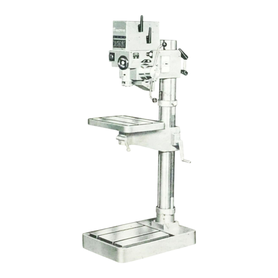
- Page 1 Z 4-03 907900B ) 0330 0 7 qua/ OPERATORS' MANUAL & REPAIR PARTS LIST Power Feed GEARED-HEAD DRILL PRESS study carefully before operating No. 24503 Floor Model wt1.'1'0N Wilton Corporation/ Machinery Division 2400 E. Devon Ave., Des Plaines, IL 60018 Telephone:...
- Page 2 HOW TO SET UP - OPERATE AND MAINTAIN NO. 24503 DRILL PRESS MECHANICAL PREPARATION Rotate the table arm assembly back under the headed lock it with the table-column locking lever. MOUNTING Unlock the head-column lock and lift the head up...
- Page 3 ELECTRICAL CONNECTIONS OPERATION SPEED SELECTION MOTOR Remove the four slotted screws at the corners of the The combination of a two speed motor and a four speed, all thermal•overload, and the thermal overload. gear, transmission provides eight drilling speeds. The motor in the low or I position developes 1.3 horsepower and in the Pull the three short wires that run between the thermal high or Il position developes 1.6 horsepower.
- Page 4 ADJUSTING THE POWER FEED OVERLOAD spindle starts to feed power feed clutc+ engages and the CLUTCH The power feed pressure is limited by an overload down. clutch in the food the drill to the gear train. Adjustments to this clutch are made as C.
- Page 5 spring housing cover and the two socket 26. Replge the Remove the two slotted screws at the corners of hend screws. speed selector switch. stop segment with a light coating of groase, 27. Cover the Pull the speed selector switch forward and out of its the stop ægment.
- Page 6 GEAR B 04 1816 1629 1806——- 182B 180B —-0 1825 1814 1809 1812 1824 1804 1808 1835 1 810 1014 1813 1810 1809 1826 ——1 1809 1834 1808 1812 1833— 1807—— 1826 1811 1819 1806 1813 1823 1804 1803 o 1822 1805 180B...
- Page 7 FEED GEAR BOX 1921 1922 1923——— 1924 1934 1925—--— 1926 1927 1937 ——1929 1938 1928 1930 1—-1941 1940 1931 1949 1948 1943 e 1944 LEVEL PLUG (A) 1945 1952—8 1946 1953— 1947 PART NO. DESCRIPTION DESCRIPTION PART NO. 1947 Cover for feed gear box Screw M 1900 (delivered together with No.
- Page 8 HEAD DESCRIPTION PART NO. 2004 2003 Frame housing + No. 1900 2000 Protection plate 2001 2002 Guide ring 2002 Sealing sleeve 2003 2001 2071 Stator 2004 2000 Motor guard 2005 Switch 2006 Reversing switch 2006 Light switch 2007 2007 2010 2008 —...
- Page 9 COLUMN, BASE, AND ARM 2100 94—-2107 2115 2108 2110 +2101 2115 2109 2111 2102 2113 '2111 2112 2109 2103 2104 2105 ——2106 2122 2119 2120 2121 2124 2123 2125 PART NO. DESCRIPTION PART NO. DESCRIPTION Lock washer 2114 Table arm 2100 2115 Locking link...
Need help?
Do you have a question about the 24503 and is the answer not in the manual?
Questions and answers