Advertisement
Quick Links
Advertisement

Related Manuals for Summit SJC


Summary of Contents for Summit SJC
- Page 1 INSTALLATION, OPERATION, AND MAINTENANCE MANUAL...
- Page 3 INSTALLATION, OPERATION, AND MAINTENANCE MANUAL I.WARRANTY Pumping units assembled by Summit Pump, Inc., Green Bay, WI are guaranteed to be free from defects in material and workmanship for one year from date of shipment from factory in Green Bay, WI. The...
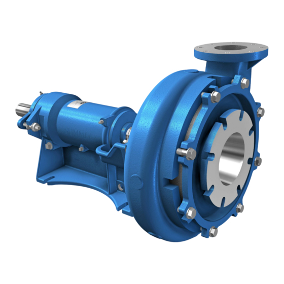
- Page 4 INSTALLATION, OPERATION, AND MAINTENANCE MANUAL SUMMIT PUMP MODEL SJC...
- Page 5 The SJC is of rotodynamic (OH-centrifugal) type. Meaning that kinetic energy is continuously transferred to the liquid by means of rotating impeller. In addition, the SJC is considered a medium duty slurry pump which can handle solids and abrasive materials within the pumped mixture.
- Page 6 1.1.5 Pump Principal The SJC pump impeller imparts liquid velocity to the casing. The casing converts the velocity energy to pressure energy and guides the liquid out the discharge. The pressure difference between the pump discharge and downline piping induces flow.
- Page 7 DANGER Pumping hazardous/toxic liquids – follow all personal protective precautions found in the MSDS. Ensure all limits are considered to avoid potential hazards such as explosion. SUMMIT PUMP MODEL SJC...
- Page 8 VFDs. SAFETY CONCERNS Summit Pump expects the end user to comply with industry and on-site safety protocols. In addition, the end user is expected to understand the product that is being supplied and all appropriate industrial standards for their application. Individuals involved in the installation, operation and maintenance (IOM) of the pumping equipment should be able to identify and eliminate unsafe environments.
- Page 9 This field is the true maximum diameter for the pump 3.1.5 ANSI No This field is not applicable to the SJC model line and will be left blank 3.1.6 MAT’L The MAT’L field will identify the material of the casing and impeller the pump was sold into commerce with.
- Page 10 Summit Pump or any representative of Summit Pump. FRAME SIZES SJC power end frame sizes are labeled by number with “1” being the smallest frame size. The frame size controls the relationship between certain parts such as, bearings, shafts, sleeves, bearing frames and housings.
- Page 11 Immediately upon arrival, carefully inspect the pump for evidence of damage during transit. Immediately report any damage to your local Summit Pump, Inc. Distributor and make a claim with the shipping carrier. Locate, read and understand all tags on the pump and installation operation and maintenance manual for the pump.
- Page 12 Figure 4-1: Pump, motor and base general lift WARNING Inspect all lifting equipment and rigging before lifting pump. Rig the pump securely ensuring a proper safety factor. Refer to Table 13-4 for pump weights. Figure 4-2: Pump general lift SUMMIT PUMP MODEL SJC...
- Page 13 5 INSTALLATION GENERAL Summit pumps are assembled at the factory. Follow all instruction tags on the pump. Ensure all fluid properties and application requirements have been considered and relayed to manufacturer and/or distributor. Suction piping should be as short and direct as possible. Electrical grounding of the pump and base assembly shall be completed.
- Page 14 Piping should be at least the same size of the pump’s suction nozzle or larger. The SJC is not a self-priming pump and must be primed with casing and suction line full of liquid prior to startup. Install one isolation valve for maintenance.
- Page 15 Normal gap is 1” to 1-1/2”. Figure 5-2: Wodden Wedges 4. Carefully lower baseplate with pump and motor onto subbase over anchor bolts. 5. Level baseplate to 0.125” over length and 0.088” over width. SUMMIT PUMP MODEL SJC...
- Page 16 V-belt life. Power sources mounted by Summit Pump are rough aligned prior to shipment. Shipping and handling may cause misalignment. Units must be checked before and after piping is attached to pump and prior to operation.
- Page 17 CAUTION Confirm pump limitations for operation and installation. NOTICE Align and Tension belts to belt manufacturer recommendations. Review Summit Pump Document SP-ENG-106: SJC BHP Limits for belt drive and engine driven power reduction calculations. SUMMIT PUMP MODEL SJC...
- Page 18 Frame Size Clearance (IC) 0.015 to All Sizes 0.031 ◦ *Note Max Allowable Working Temperature is 250 The impeller clearances shown in Table 6-1 Figure 6-1: Impeller Clearance "IC" can be set when pump is at ambient SUMMIT PUMP MODEL SJC...
- Page 19 (134A). A skewed bearing housing (134A) can increase loading on the thrust bearing (112C) leading to shorter life. 5. Tighten IB nuts (415) to the bearing frame (228) ears. Torque all four nuts (415) to values in Table 12-1 on page 51. 0.000 Figure 6-2: Dial indicator method SUMMIT PUMP MODEL SJC...
- Page 20 STUFFING BOX The stuffing box comes standard with packing, and mechanical seals are optional. The SJC pump are designed for medium duty slurry applications and pumped liquid should be kept away from packing or rotating mechanical seal faces. The common way to accomplish this is to introduce clean liquid such as water into the stuffing box at a higher pressure than the stuffing box pressure without the clean liquid flush.
- Page 21 The SJC pump is considered a medium duty slurry pump and is expected to see abrasive particles in the stuffing box area. The abrasiveness of these particles can lead to premature wear of the seal faces. To reduce this wear a clean liquid flush may be necessary.
- Page 22 Never add oil to grease lubricated pumps. SJC pumps are standard grease lubricated, as an option oil lubrication is available. Oil lubricated pumps are not shipped with oil from the factory. Oil must be added prior to the first startup.
- Page 23 GREASE FITTINGS Figure 6-8: Grease fitting locations 6.5.2 OIL LUBRICATION Oil lubrication for the SJC is an option and comes with a breather, a vented constant level oiler and pipe fittings. Oiler is shipped loose from assembled pump to BREATHER avoid damage in transport.
- Page 24 INSTALLATION, OPERATION, AND MAINTENANCE MANUAL Table 6-3: Oiler part list SJC STANDARD VENTED OILER ITEM DESCRIPTION TOP CASTING & BULB LOWER CASTING ADJUSTMENT STUD LOCKING TANG LEVELING TANG PLUG LOCKING KNOB Figure 6-10: Oiler components 6.5.2.2 Installing the oiler Install the pipe fittings as shown in Figure 6-11. Use a hydraulic thread sealant on all threads and not a PTFE based thread sealant or tape.
- Page 25 INSTALLATION, OPERATION, AND MAINTENANCE MANUAL DATUM Figure 6-14: Oiler height setting Table 6-4: Oiler setting dimensions SJC Oiler Setting Dimensions Dimension Frame 1 Frame 2 Frame 3 Frame 4 (INCHES) 4.82 5.43 5.98 6.54 4.75 5.25 5.76 6.25 Once the correct height of the top casting (A) is determined, tighten locking tang (D.A) against leveling tang (D.B).
- Page 26 2/3 to 3/4 full of oil. Quickly rotate top casting (A) over to install on to lower casting (B). Tighten the locking knob (F) to secure Figure 6-16: Adding Oil top casting (A) in place. Figure 6-17:Fill oil in top casting (A) SUMMIT PUMP MODEL SJC...
- Page 27 Energize the driven components and bring pump to operating speed as quickly as possible. Read the flow and pressure gauges, compare with expected. Adjust system components as needed, never control flow with valve on suction side. If unable to achieve expected flow and head, record flow and pressures then shut down the pump. SUMMIT PUMP MODEL SJC...
- Page 28 Stuffing box gland is too tight Liquid SG is heavier than specified Suction piping does not have straight unobstructed pipe before pump Stuffing Box is packed incorrectly Entrance velocity in suction is too high for submergence Impeller diameter different than expected SUMMIT PUMP MODEL SJC...
- Page 29 2. Check and compare pump performance with published performance curve and previous data recordings of the pump. These inspections can range from once a year, to once every three to five years. RECOMMENDED SPARE PARTS Table 7-1: SJC Recommended Spare Parts MODEL SJC SLURRY PUMP ITEM...
- Page 30 Example: Casing (100). Pump Working Components 412F 100B 528K 496A 370E See Power End View See Sealing View Figure 8-1: Pump Working Components – See note in section 8.4 SUMMIT PUMP MODEL SJC...
- Page 31 134A 112C 193B 356A 408C 408B 415 528P Figure 8-2: Power End Frame 1 thru 4 greased lubricated 8.2.1 Frame 5 112D 112C 134A 193B 356A 415 528P Figure 8-3: Power End Frame 5 greased lubricated SUMMIT PUMP MODEL SJC...
- Page 32 INSTALLATION, OPERATION, AND MAINTENANCE MANUAL Sealing Components 528L 370J 528J 370C Figure 8-4: Sealing Components - See note in section 8.4 Parts List Table 8-1: Parts List, Item Number identifier. MODEL SJC SLURRY PUMP ITEM DESCRIPTION ITEM DESCRIPTION ITEM DESCRIPTION CASING SUCTION COVER...
- Page 33 INSTALLATION, OPERATION, AND MAINTENANCE MANUAL Assembled Cross Section 370J 370E 528L 528K 123C 356A 528P 415 134A 168C 119B 112C 528P 356A 412F 101 100B Figure 8-5: Assembled cross section TOP view. Refer to Table 8-1. SUMMIT PUMP MODEL SJC...
- Page 34 Use the following steps as a general guideline, as it is impractical to cover every situation considering the possible conditions of the pump. Notes: SJC pumps may have a mechanical seal. This section will only consider packing. Refer to the seal • manufacturer’s instructions for disassembly and assembly.
- Page 35 (101) counter- clockwise when viewing the pump from the impeller side. 5. Check for wear or damage on Figure 9-2: Impeller (101) Removal impeller (101), replace if necessary. SUMMIT PUMP MODEL SJC...
- Page 36 (184). Check for wear 528J or damage and replace if needed. 6. Remove the packing (106) and lantern ring (105) from the stuffing box cover (184). Replace packing for reassembly. Figure 9-4: Sealing Components Disassembled SUMMIT PUMP MODEL SJC...
- Page 37 Figure 9-5: Remove Shaft Kit from bearing frame (228) 8. Slide the bearing housing (134A) off the thrust bearing (112C) and shaft (122) being careful not to damage the lip seal (332) if planning to reuse. SUMMIT PUMP MODEL SJC...
- Page 38 (112C & 168C) can damage the shaft (122) at bearing locations. NOTE: SJC Frame 5 will have two bearings (112D & 112C) on the outboard end of the shaft (122) separated by a collar (237). The removal...
- Page 39 • individual parts and finish with a fully assembled bare pump without other auxiliary equipment. SJC frame 5 has one extra radial bearing (112D) and bearing collar (237) on the coupling end of the shaft. • All other frame sizes will follow the same procedure.
- Page 40 B. Install bearing collar (237) against the bearing (112C). Let collar (237) cool to ambient temperature. C. Install the radial bearing (112D) against the bearing collar with identification numbers facing towards coupling end of shaft (122). SUMMIT PUMP MODEL SJC...
- Page 41 (332) will not be visible once pump is assembled. Lubed 6. Lubricate O-Ring (496) with bearing oil or grease. Install over bearing housing (134A) into groove. SEALING LIP FACES OU T Figure 10-5: Seal (332) Orientation SUMMIT PUMP MODEL SJC...
- Page 42 (332) and inner diameter of the end cover (119B). If bearings are to be 119B 119B Figure 10-7: Press fit End Cover (119B) into bearing frame Figure 10-6: Lubricate and squarely set End Cover (228) (119B) to bore. SUMMIT PUMP MODEL SJC...
- Page 43 (119B) sets inside the lip of the deflector (123C) but does not rub. Tighten set screws (222) to shaft (122) and torque to values in Table 12-1 on page 51. Figure 10-10: Secure bearing housing (134A) SUMMIT PUMP MODEL SJC...
- Page 44 (106). Tamp each packing ring (106) after installing it in the stuffing box. 25. Install the packing gland studs (353) into the stuffing box cover (184). 26. Install packing gland (107) over the sleeve (126) and over the packing gland studs (353). SUMMIT PUMP MODEL SJC...
- Page 45 (370J) in a crisscross pattern. Follow the same pattern about three times increasing torque values each time until torque values in Table 12-1 are met with two Figure 10-13: Install Casing (100) with lift assist pattern passes. SUMMIT PUMP MODEL SJC...
- Page 46 Follow the same pattern about three times increasing torque values each time until torque values in Table 12-1 are met with two pattern passes. 100B Set the impeller clearance per section 6.1 on page 18. Figure 10-17: Suction Cover (182) install SUMMIT PUMP MODEL SJC...
- Page 47 INSTALLATION, OPERATION, AND MAINTENANCE MANUAL 11 Barrel Type Coupling Guards Summit Pump manufactured barrel type coupling guards come as an option to the SJC pump. Assembly and disassembly instructions shall be followed as described in this manual. If a separate manual is supplied with the guard these instructions are superseded.
- Page 48 Figure 11-3: Assemble motor end plate and install over motor shaft 6. Slide one guard shroud (531C) inside the other guard shroud (531C). Holding both shrouds (531C) at the flanged opening, separate the flanges and install over the pump and motor shaft, if applicable. SUMMIT PUMP MODEL SJC...
- Page 49 10. Slide the guard shrouds (531C) apart from each other to desired distance 531G 531H from the motor. 531F 11. Tighten nuts (531G) and bolts Figure 11-5: Fasten guard and set clearance to motor (531F). SUMMIT PUMP MODEL SJC...
- Page 50 INSTALLATION, OPERATION, AND MAINTENANCE MANUAL SUMMIT PUMP MODEL SJC...
- Page 51 INSTALLATION, OPERATION, AND MAINTENANCE MANUAL 12 APPENDIX A: HARDWARE 12.1 Hardware List Note: Torque values are based on dry fit non-lubricated threads. Table 12-1: SJC Hardware list unlubricated Steel Stainless Fastener Qty Per Stainless Item ID Description Pump Size Length...
- Page 52 3/8" NPT Steel 316SS or CD4 2*TFFT 2*TFFT 408B Plug, Bearing Frame Drian All Frames 3/4" NPT Steel 2*TFFT 408C Plug, Bearing Oil Level All Frames 1/4" NPT Steel 2*TFFT TFFT = Turns From Finger Tight SUMMIT PUMP MODEL SJC...
- Page 53 13 APPENDIX B: ENGINEERING DATA 13.1 SHAFT SLEEVES Prior to year 2024 Summit Pump manufactured shaft sleeves for packing and mechanical seals in different lengths (“L”). The shorter length sleeve was for packing and the longer length sleeve for mechanical seals.
- Page 54 INSTALLATION, OPERATION, AND MAINTENANCE MANUAL 13.2 MATERIALS OF CONSTRUCTION Standard pump materials are generalized below. Check with the local Summit Pump Distributor for the construction material of an existing pump via the serial number. When ordering a new pump and no materials are specified the standard materials will be used.
- Page 55 INSTALLATION, OPERATION, AND MAINTENANCE MANUAL 13.3 ENGINEERING DATA Table 13-4: Engineering data SJC Frame Size: Weight (lbs): 1020 1800 Maximum Solid Size (in): 1 1/8 1 1/8 1 3/8 1 1/2 1 1/2 2 1/4 2 1/4 1.43 3.43 8.62 BHP/100 RPM: 11.43...
- Page 56 INSTALLATION, OPERATION, AND MAINTENANCE MANUAL 14 APPENDIX C: DIMENSIONAL DATA 14.1 PUMP DISCHARGE FLANGE SUCTION FLANGE QTY (2) 3/8-18 NPT VIEW J-J Figure 14-1: Pump Dimensions SUMMIT PUMP MODEL SJC...
- Page 57 8 : 7/8 9 1/2 8 : 7/8 8x10-18 2.63 2.26 0.63 5.81 14 1/4 12 : 1 13 1/2 11 3/4 8: 7/8 10x12-22 3.00 2.57 0.75 6.50 12 : 1 14 1/4 12 : 1 SUMMIT PUMP MODEL SJC...
- Page 58 QTY (2) 1/2"-13 2.875 3.375 4.375 5.500 3.500 2 7/8 QTY (5) 1/2" QTY (2) 1/2"-13 3.437 4.125 5.375 7.125 4.500 QTY (5) 5/8" QTY (2) 5/8"-11 NOTE: "OB" TO BE USED AS MINIMUM FOR MECHANICAL SEALS SUMMIT PUMP MODEL SJC...
- Page 59 INSTALLATION, OPERATION, AND MAINTENANCE MANUAL 15 PUMP INFORMATION Purchase Date: ________________________ Purchase Order: ___________________ Serial Number: _____________________ Equipment Number: _________________ SUMMIT PUMP MODEL SJC...
- Page 60 INSTALLATION, OPERATION, AND MAINTENANCE MANUAL PO Box 12145 Green Bay, WI 54307 www.summitpump.com Rev. 01/2025 SUMMIT PUMP MODEL SJC...
Need help?
Do you have a question about the SJC and is the answer not in the manual?
Questions and answers