Advertisement
Quick Links
CAUTION, MICROWAVE RADIATION .......................................................................... Inside front cover
WARNING ................................................................................................................................................. 3
SERVICING ............................................................................................................................................. 4
GENERAL INFORMATION ....................................................................................................................... 6
PRODUCT SPECIFICATIONS/ TEST DATA AT A GLANCE ................................................................... 7
APPEARANCE VIEW .............................................................................................................................. 7
OPERATION SEQUENCE ........................................................................................................................ 9
FUNCTION OF IMPORTANT COMPONENTS ..................................................................................... 11
TROUBLESHOOTING GUIDE ............................................................................................................... 13
TEST PROCEDURE .............................................................................................................................. 14
CONTROL PANEL ASSEMBLY ............................................................................................................ 21
COMPONENT REPLACEMENT AND ADJUSTMENT PROCEDURE .................................................. 26
MICROWAVE MEASUREMENT ........................................................................................................... 32
SCHEMATIC DIAGRAM ........................................................................................................................ 36
PICTORIAL DIAGRAM .......................................................................................................................... 36
POWER UNIT CIRCUIT DIAGRAM ........................................................................................................ 37
PRINTED WIRING OF JOG SWITCH UNIT ........................................................................................... 38
PRINTED WIRING BOARD OF JOG SWITCH UNIT ............................................................................. 38
CPU UNIT CIRCUIT OF POWER UNIT ................................................................................................. 39
PRINTED WIRING BOARD OF POWER UNIT ...................................................................................... 40
PARTS LIST .......................................................................................................................................... 41
EXPLODED DIAGRAMS ........................................................................................................................ 43
SERVICE MANUAL
®
MODELS
In interests of user-safety the oven should be restored to its original
condition and only parts identical to those specified should be used.
TABLE OF CONTENTS
SHARP CORPORATION
R-775(W)R-785(AL) - 1
MICROWAVE OVEN WITH
TOP AND BOTTOM GRILLS
R-775(W)
R-785(AL)
S50220R775EHW
Page
Advertisement

Subscribe to Our Youtube Channel
Related Manuals for Sharp R-775W


Summary of Contents for Sharp R-775W
- Page 1 PRINTED WIRING OF JOG SWITCH UNIT ................... 38 PRINTED WIRING BOARD OF JOG SWITCH UNIT ................38 CPU UNIT CIRCUIT OF POWER UNIT ....................39 PRINTED WIRING BOARD OF POWER UNIT ..................40 PARTS LIST ............................41 EXPLODED DIAGRAMS ........................43 SHARP CORPORATION R-775(W)R-785(AL) - 1...
- Page 2 CAUTION CAUTION MICROWAVE RADIATION Personnel should not be exposed to the microwave energy which may radiate from the magnetron or other microwave generating devices if it is improperly used or connected. All input and output microwave connections, waveguides, flanges and gaskets must be secured.
- Page 3 GENERAL IMPORTANT INFORMATION This Manual has been prepared to provide Sharp Corp. Service engineers with Operation and Service Information. It is recommended that service engineers carefully study the entire text of this manual, so they will be qualified to render satisfactory customer service.
- Page 4 Sharp beveelt ten sterkste aan dat, voor zover mogelijk, defecten worden opgespoord wanneer de stekker uit het Wanneer alle reparaties zijn uitgevoerd en de oven weer in stopcontact is gehaald.
- Page 5 är kallt utför Du 3 steg kontroller och kontrollerar anslutningarna till varje enskild komponent på nytt. Sharp rekommenderar att felsökning sker med strömmen fränkopplad. Ibland kan det var nödvändigt att koppla på När all service är klar och ugnen ihopskruvad skall ugnens strömmen efter det att höljet avlägsnats, utför da 3 Steg...
- Page 6 Sharp raccomanda, nei limiti del possibile, che la ricerca dei guasti avvenga in assenza di alimentazione elettrica. In alcuni casi tuttavia, può essere necessario alimentare Dopo aver portato a termine le operazioni di manutenzione l'apparecchio dopo aver rimosso la scatola esterna.
- Page 7 PRODUCT DESCRIPTION SPECIFICATION ITEM DESCRIPTION Power Requirements 230 Volts / 50 Hertz / Single phase, 3 wire earthed Power Consumption Microwave cooking 1.45 kW Approx. 6.5 A Top Grill mode ...... 1.25 kW Approx. 5.4 A Grill cooking Bottom Grill mode ....0.65 kW Approx.
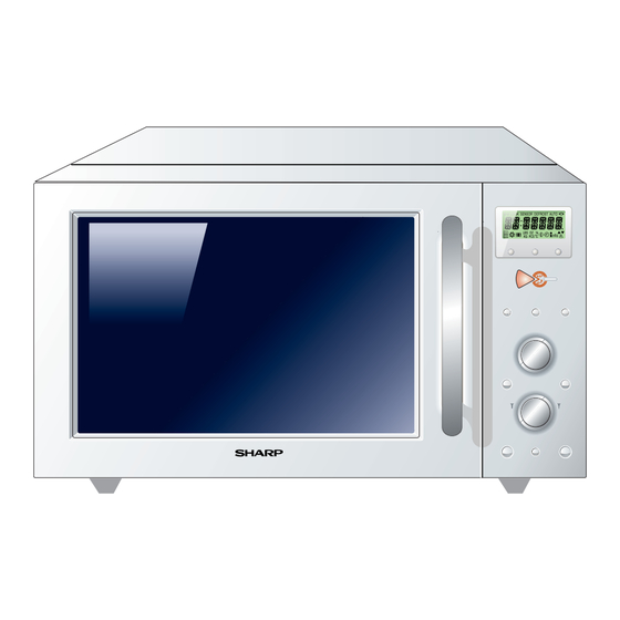
- Page 8 APPEARANCE VIEW OVEN 1. Control panel 2. Oven lamp 3. Grill heating element (Top Grill) 4. Waveguide cover 8. Door seals and sealing surfaces 5. Oven cavity 9. Door opening handle 13.Turntable 6. Turntable motor shaft 10.Ventilation openings 14.Low rack 7.
- Page 9 OPERATION SEQUENCE OFF CONDITION to negative voltage of approximately 4000 volts D.C.. 3. The 2450 MHz microwave energy produced in the Closing the door activates the monitored latch switch SW1 magnetron generates a wavelength of 12.24 cm. This the stop switch SW2 and the monitor switch SW3. energy is channelled through the waveguide (transport IMPORTANT: channel) into the oven cavity, where the food is placed...
- Page 10 OPERATION SEQUENCE MEDIUM HIGH, MEDIUM, MEDIUM LOW, LOW 1. The numbers on the digital readout start the count down to zero. COOKING 2. The oven lamp, cooling fan motor and turntable motor When the microwave oven is preset for variable cooking are energized.
- Page 11 OPERATION SEQUENCE AUTOMATIC COOKING Specified cooking Limited power Cooking mode time (minutes) output (%) AUTO COOK, EXPRESS PIZZA, PIZZA Microwave (100%) AUTO DEFROST, FUN MENUS Above functions are automatic cooking. They automati- Top grill cally work out the correct cooking mode and time for Bottom grill cooking.
- Page 12 FUNCTION OF IMPORTANT COMPONENTS CAUTION: BEFORE REPLACING A BLOWN FUSE F2 current flow in both directions. It prevents the temperature F8A, TEST THE MONITORED LATCH rise of the high voltage transformer by blowing the fuse F2 SWITCH SW1 AND MONITOR SWITCH F8A when the high voltage rectifier is shorted.
- Page 13 TROUBLESHOOTING GUIDE BLOCKED COOLING FAN BLOCKED CONVECTION FAN NO POWER AT WALL OUTLET HOME FUSE OR BREAKER MIS-ADJUSTMENT OF SWITCHES BLOCKED VENTILATION OPENINGS OPENED WIRE HARNESS SHORTED WIRE HARNESS OVEN LAMP POWER SUPPLY CORD FOIL PATTERN ON P.W.B. RELAY RY6 RELAY RY4 RELAY RY5 RELAY RY3...
- Page 14 TEST PROCEDURES PROCEDURE COMPONENT TEST LETTER MAGNETRON TEST NEVER TOUCH ANY PART IN THE CIRCUIT WITH YOUR HAND OR AN INSULATED TOOL WHILE THE OVEN IS IN OPERATION. CARRY OUT 3D CHECKS. Isolate the magnetron from high voltage circuit by removing all leads connected to filament terminal. To test for an open circuit filament use an ohmmeter to make a continuity test between the magnetron filament terminals, the meter should show a reading of less than 1 ohm.
- Page 15 TEST PROCEDURES PROCEDURE COMPONENT TEST LETTER Room temperature ....... To = 21˚C Initial temperature ..... T1 = 11°C Temperature after (47 + 3) = 50 sec..............T2 = 21°C Temperature difference Cold-Warm ..............∆T1 = 10°C Measured output power The equation is “P = 90 x ∆T”...
- Page 16 TEST PROCEDURES PROCEDURE COMPONENT TEST LETTER CARRY OUT 4R CHECKS. NOTE: FOR MEASUREMENT OF THE RESISTANCE OF THE RECTIFIER, THE BATTERIES OF THE MEASURING INSTRUMENT MUST HAVE A VOLTAGE AT LEAST 6 VOLTS, BE- CAUSE OTHERWISE AN INFINITE RESISTANCE MIGHT BE SHOWN IN BOTH DIREC- TIONS.
- Page 17 TEST PROCEDURES PROCEDURE COMPONENT TEST LETTER MOTOR WINDING TEST CARRY OUT 3D CHECKS. Disconnect the leads from the motor. Using an ohmmeter, check the resistance between the two terminals as described in the table below. Table: Resistance of Motor Motors Resistance Fan motor Approximately...
- Page 18 TEST PROCEDURES PROCEDURE COMPONENT TEST LETTER GRILL HEATING ELEMENT (TOP) AND BOTTOM HEATING ELEMENTS TEST CARRY OUT 3D CHECKS. Before carrying out the following tests make sure the heating element is cool completely. 1. Resistance of heating element. Disconnect the wire leads to the heating element to be tested. Using ohmmeter with low resistance range.
- Page 19 TEST PROCEDURES PROCEDURE COMPONENT TEST LETTER JOG SWITCH UNIT TEST If the display fails to clear when the STOP button is depressed, first verify the cable is marking good contact, verify that the stop switch operates properly; that is the contacts are closed when the door is closed and open when the door is open.
- Page 20 TEST PROCEDURES PROCEDURE COMPONENT TEST LETTER PROCEDURES TO BE TAKEN WHEN THE FOIL PATTERN ON THE PRINTED WIRING BOARD (PWB) IS OPEN To protect the electronic circuits, this model is provided with a fine foil pattern added to the input circuit on the PWB, this foil pattern acts as a fuse.
- Page 21 TOUCH CONTROL PANEL ASSEMBLY OUTLINE OF TOUCH CONTROL PANEL The touch control section consists of the following units as order to compose a basic standard time in the clock shown in the touch control panel circuit. circuit. It accompanies a very small error because it works on commercial frequency.
- Page 22 DESCRIPTION OF LSI The I/O signal of the LSI are detailed in the following table. Pin No. Signal Description Terminal not used. Power source voltage input terminal. Standard voltage for LCD. Terminal to change the ON timing of the cook relay (RY2). AN6-AN5 Heating constant compensation terminal.
- Page 23 DESCRIPTION OF LSI The I/O signal of the LSI are detailed in the following table. Pin No. Signal Description 29-32 P75-P72 Terminal not used. Signal coming from encoder. Signal similar to INT1. Pulse signals are input into P24. INT0 Signal coming from encoder. When the encoder is turned, the contacts of encoder make pulse signals.
- Page 24 DESCRIPTION OF LSI The I/O signal of the LSI are detailed in the following table. Pin No. Signal Description Oven lamp and turntable motor driving signal(Square Waveform : 50Hz). To turn on and off shut-off relay (RY1). The square waveform voltage is 20 msec.
- Page 25 SERVICING 1. Precautions for Handling Electronic Components 4) Re-install the outer case (cabinet). This unit uses CMOS LSI in the integral part of the circuits. 5) Re-connect the power supply cord after the outer When handling these parts, the following precautions case is installed.
- Page 26 Oven lamp, Magnetron, High voltage transformer To prevent an electric shock, take the following and Oven cavity. measures. 3) Sharp edge: 1. Before wiring, Bottom plate, Oven cavity, Weveguide flange, 1) Disconnect the power supply. Chassis support and other metallic plate.
- Page 27 COMPONENT REPLACEMENT AND ADJUSTMENT PROCEDURE 6. Remove one (1) screw holding capacitor holder to the 11.Now, the high voltage rectifier assembly and the high oven cavity rear plate. voltage capacitor should be free. 7. Release the capacitor holder from the fan duct. CAUTION: WHEN REPLACING HIGH VOLTAGE 8.
- Page 28 4. Cut the four (4) bridges holding the turntable motor Re-install cover to the base plate with cutting pliers as shown in 1. Remove the any sharp edges on the turntable motor Figure C-2(a). cover and the base plate with the cutting pliers.
- Page 29 COMPONENT REPLACEMENT AND ADJUSTMENT PROCEDURE Screw; Cutting pliers LX-EZA045WRE0 Turntable motor cover Tabs Bridges Bridges Turntable motor Slits cover Base plate Figure C-2(a). Turntable motor cover removal FigureC-2(b). Turntable motor cover re-install OVEN LAMP SOCKET REMOVAL 1. CARRY OUT 3D CHECKS. 2.
- Page 30 COMPONENT REPLACEMENT AND ADJUSTMENT PROCEDURE MONITORED LATCH SWITCH, MONITOR SWITCH AND STOP SWITCH REMOVAL 1. CARRY OUT 3D CHECKS. 2. Remove the control panel assembly referring to "CON- TROL PANEL ASSEMBLY REMOVAL". SW2: Stop switch 3. Disconnect the leads from all switches. 4.
- Page 31 COMPONENT REPLACEMENT AND ADJUSTMENT PROCEDURE DOOR REPLACEMENT REMOVAL Note: After any service to the door; 1. Disconnect the oven from the power supply. (A) Make sure that the monitor switch, monitored 2. Pull open the door slightly. latch switch and stop switch are operating prop- 3.
- Page 32 MICROWAVE MEASUREMENT After adjustment of door latch switches, monitor switch 2. Place the oven tray into the oven cavity. and door are completed individually or collectively, the 3. Place the load of 275 ± 15ml of water initially at 20 following leakage test must be performed with a survey ±...
- Page 33 SCHEMATIC DIAGRAM Note: SCHEMATIC AC CORD CONNECTION NOTE: CONDITION OF OVEN BRN : BROWN 1. DOOR CLOSED. BLU : BLUE 2. PLUGGED IN OVEN. G-Y : GREEN AND YELLOW STRIPE 3. NOTHING APPEARS ON DISPLAY. /15 : SECTIONAL AREA OF 1.5mm MIN.
- Page 34 SCHEMATIC DIAGRAM SCHEMATIC NOTE: CONDITION OF OVEN 1. DOOR CLOSED. Indicates components with potential above 250 V. 2. MICROWAVE MODE SET. 3. COOKING TIME SET. 4. STRAT BUTTON PRESSED. NOISE FILTER F2: FUSE F8A TC1: THERMAL CUT-OUT CONTROL UNIT TC2: OVEN SW2: THERMAL...
- Page 35 SCHEMATIC DIAGRAM SCHEMATIC NOTE: CONDITION OF OVEN 1. DOOR CLOSED. TOP & BOTTOM GRILL MODE SET. 3. COOKING TIME SET. 4. STRAT BUTTON PRESSED. NOISE FILTER F2: FUSE F8A TC1: THERMAL CUT-OUT CONTROL UNIT TC2: OVEN THERMAL SW2: CUT-OUT STOP SWITCH SW3: ASYMMETRIC MONITOR...
- Page 36 PICTORIAL DIAGRAM R-775(W)R-785(AL) - 36...
- Page 37 POWER UNIT CIRCUIT DIAGRAM D11-D14 1N4005E 1N4004S WH1-4 WH1-3 – – R4 510 1w WH1-6 R3 510 1w R5 3.3k WH1-9 BUZZER AC230V 50Hz WH1-10 WH1-5 POWER WH1-11 CONTROL FAN MOTOR WH1-8 WH1-7 R6 200 1w OVEN LAMP TURNTABLE MOTOR BOTTOM WH1-12 HEATING...
- Page 38 PRINTED WIRING/BOARD OF JOG SWITCH UNIT DIAGRAM J-13 J-12 RSW1 ROTARY ENCODER J-11 J-10 VR1 POTENTIOMETERS J - 9 SW13 SW12 J - 1 J - 2 J - 5 J - 6 DCUT J - 3 SW11 J - 4 SW12 EXPRESS SW10...
- Page 39 CPU UNIT CIRCUIT DIAGRAM COOK SENSOR DEFROST AUTO ˚C R-775(W)R-785(AL) - 39...
- Page 40 PRINTED WIRING BOARD OF POWER UNIT DIAGRAM (J2) VRS1 POWER CONT Figure S-6. Printed Wiring Board of Power Unit HOW TO ORDER REPLACEMENT PARTS To have your order filled promptly and correctly, please furnish the following information. 1. MODEL NUMBER 3.
- Page 41 PARTS LIST Note: The parts marked " ∆ " may cause undue microwave exposure. / The parts marked "*" are used in voltage more than 250V. / "§" Mark: Spare parts delivery section REF. NO. PART NO. § DESCRIPTION Q'TY CODE ELECTRIC PARTS RC-QZA240WRE0 High voltage capacitor...
- Page 42 PARTS LIST Note: The parts marked " ∆ " may cause undue microwave exposure. / The parts marked "*" are used in voltage more than 250V. / "§" Mark: Spare parts delivery section REF. NO. PART NO. § DESCRIPTION Q'TY CODE OVEN PARTS 4- 1 DOVN-A022URK0...
- Page 43 OVEN PARTS 7-12 4-14 7-12 7-12 7-13 7-12 7-12 7-12 7-12 4-18 7-13 4-18 4-24 7-12 4-16 7-12 7-10 7-14 4-11 4-23 4-17 4-10 4-22 4-13 7-12 4-12 4-15 7-11 4-19 4-21 7-12 4-20 NOTE: In the event of removing the turn- table motor cover this part should 7-12 be refitted using screw connec-...
- Page 44 CONTROL PANEL/DOOR PARTS CONTROL PANEL PARTS 3-15 3-15 3-11 3-14 3-12 3-15 3-15 3-15 3-13 3-10 DOOR PARTS 5-11 5-12 5-10 5-10 R-775(W)R-785(AL) - 44...
- Page 45 MISCELLANEOUS/PACKING& ACCESSORIES PARTS MISCELLANEOUS Actual wire harness may be different than illustration. PACKING & ACCESSORIES TOP PAD ASSEMBLY (FPADBA018URK0) PROTECTION SHEET (SPADPA024URE0) LOW RACK WRAP COVER for R-785(AL) (SPADFA353WRE0) HIGH RACK DOOR PROTECTION SHEET TURNTABLE TRAY (SPADPA020WRE0) PRINTED MATTER BOTTOM PAD ASSEMBLY ACCESSORY HOLDER (FPADBA019URK0) (SPADPA015URE1)
- Page 46 ® '2002 SHARP CORP. Printed in U.K. R-775(W)R-785(AL) - 46...
Need help?
Do you have a question about the R-775W and is the answer not in the manual?
Questions and answers