Advertisement
Quick Links
AudioMaster
Public Address High-Powered Amplifiers
®
Models CTS2-300, CTS2-600, CTS2-1250, CTS2-300N, CTS2-600N
CTS2-1250N, CTS2-2400N
Description, Specifications,
Installation, and Operation Manual
25500415
Rev. A0 0717
Printed in U.S.A.
© Copyright 2017 Federal Signal Corporation
Advertisement

Related Manuals for Federal Signal Corporation AudioMaster CTS2-300


Summary of Contents for Federal Signal Corporation AudioMaster CTS2-300
- Page 1 AudioMaster Public Address High-Powered Amplifiers ® Models CTS2-300, CTS2-600, CTS2-1250, CTS2-300N, CTS2-600N CTS2-1250N, CTS2-2400N Description, Specifications, Installation, and Operation Manual 25500415 Rev. A0 0717 Printed in U.S.A. © Copyright 2017 Federal Signal Corporation...
- Page 2 A copy of this limited warranty can also be obtained by written request to Federal Signal Corporation, 2645 Federal Signal Drive, University Park, IL 60484, email to info@fedsig.com or call +1 708-534-3400.
- Page 3 Contents Safety Messages..............................8 FCC Compliance Notice .............................9 Declaration of Conformity ..........................10 EMC Standards ..............................10 Safety Standard ..............................11 General Description ..............................12 Introduction ..............................12 CTS2 Specifications ..............................12 Features for All Models .............................12 Features (Network Capable Models) ........................13 Front Panel Features ............................13 Indicators ..............................13 Back Panel Features (CTS2-300, CTS2-600, CTS2-1250) ................14 Back Panel Features (CTS2-300N, CTS2-600N, CTS2-1250N) ..............15...
- Page 4 Fan-cooled Chassis ..........................22 Universal Switching Power Supply ......................22 8a. Setup and System Configuration (CTS2-300, CTS2-600, CTS2-1250) ............22 Global Settings ............................22 Connect Loudspeakers and Configure for Loudspeaker Load ..............23 Determine load impedances and power requirements ................23 Dual Mode Low-Z (8, 4, or 2 Ohm) ......................23 Bridge Mode (16, 8, or 4 Ohm) .........................24 Dual Mode Hi-Z (70V/100V) ........................25 Bridge Mode Hi-Z (140V/200V) .........................26...
- Page 5 Tables Table 1 CTS2 Specifications ..........................12 Table 2 Front Panel Visual Indications ........................13 Table 3 Back Panel Features (CTS2-300, CTS2-600, CTS2-1250) ..............14 Table 4 Back Panel Features (CTS2-300N, CTS2-600N, CTS2-1250N) .............. 15 Table 5 Back Panel Features (CTS2-2400N) ......................16 Table 6 Wire Size Guidelines ..........................19 Table 7 Channel Attenuators ..........................21 Table 8 Total Latency ............................62 Table 9 Dual-Mode - All Channels Driven ......................79...
- Page 6 Table 27 CTS2- 2400N - Bridge ..........................88 Table 28 CTS2-2400N - Dual ..........................89 Figures Figure 1 Font of Amplifier .............................14 Figure 2 CTS2 Channel Series Dimensions ......................18 Figure 3 Airflow ..............................18 Figure 4 Balance and Unbalance Input Connector Wiring ................19 Figure 5 Typical Output Connector Wiring ......................20 Figure 6 System Wiring Dual Mode ........................23 Figure 7 System Wiring Bridge Mode ........................24...
- Page 7 Figure 27 System Wiring for 70 Vrms/100 Vrms Operation ................49 Figure 28 Amplifier Mode Settings-Dual Mode Hi-Z ...................49 Figure 29 System Wiring for 140 Vrms/200 Vrms Operation ................50 Figure 30 Amplifier Mode Settings-Bridge Mode Hi-Z ..................50 Figure 31 Control Port Configuration Page ......................52 Figure 32 Assigning the “Current Preset”...
- Page 8 Safety Messages Safety Messages It is important to follow all instructions shipped with this product. This device is to be installed by trained personnel who are thoroughly familiar with the country electric codes and will follow these guidelines as well as local codes. 1.
- Page 9 Safety Messages 17. Do not expose this equipment to dripping or splashing and ensure that no objects filled with liquids, such as vases, are placed on the equipment. 18. The mains plug of the power supply cord shall remain readily operable. Safety Messages to Installers •...
- Page 10 Safety Messages • Connect the equipment into an outlet on a circuit different from that to which the receiver is connected. • Consult the dealer or an experienced radio/TV technician for help. Declaration of Conformity Our products meet the appropriate British and International standards. A product Declaration of Conformity statement is available for each of the product ranges (available on request).
- Page 11 Safety Messages Safety Standard EN60065:2002 +A12:2011, IEC 60065:2001 Ed 7 +A1:2005 +A2:2010 Safety Requirements – Audio, Video, and Similar Electronic Apparatus CAN/CSA 60065-03 incl. A1 Safety Requirements – Audio, Video, and Similar Electronic Apparatus UL Std No. 60065-2007 Safety Requirements – Audio, Video, and Similar Electronic Apparatus The product identified above conforms to the requirements of the EMC Council Directive 2004/108/EC and the Low Voltage Directive 2006/95/EC.
- Page 12 General Description General Description Introduction The Federal Signal CTS2 Series offers new flexibility and value for installed sound. The Com-Tech Series was the first to offer independent selection of high- and low- impedance operation for a specific channel, and CTS2 Series amplifiers continue that tradition, with power levels and features carefully chosen to perfectly integrate into fixed install design requirements.
- Page 13 CTS2 Specifications • Advanced Protection Circuits – Amplifier and loads are protected against shorted outputs, DC, mismatched loads, overheating, over- or under-voltage, and high frequency overload. • Five Year, No-Fault Transferable Warranty – Your investment is fully protected. • PFC Power Supply – the next generation power supply design guarantees minimum rated power delivered for drastically lower current draw.
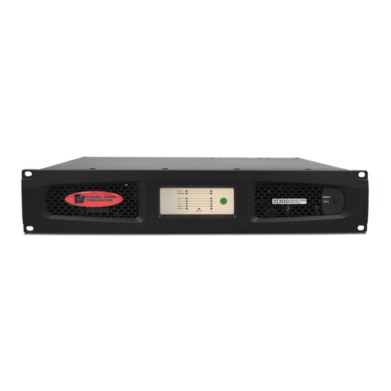
- Page 14 CTS2 Specifications Features Description Data Indicator Illuminates when data present on the data network only. BLU link (yellow) connectivity is not a part of this indicator. Power Button Power Ring Indicator (Green) - Illuminates when the amplifier is plugged into a wall outlet with acceptable power. NOTE: Power Button is disabled when AUX port Sleep circuit is used.
- Page 15 CTS2 Specifications Global Input Connectors Mode DIP Input Attenuators Power Fuse Setting Switches AC Power Inlet Auxiliary Connector Cooling Fan Outlet Output Connectors Back Panel Features (CTS2-300N, CTS2-600N, CTS2-1250N) Table 4 Back Panel Features (CTS2-300N, CTS2-600N, CTS2-1250N) Features Description Power Fuse F20AH 250V, replace with same type fuse.
- Page 16 CTS2 Specifications BLU link Ethernet Input Connectors Power Fuse Input Attenuators General Purpose Auxiliary Connector AC Power Inlet Output Connectors Cooling Fan Outlet Back Panel Features (CTS2-2400N) Table 5 Back Panel Features (CTS2-2400N) Features Description Cooling Fan Outlet Outlets for cooling air flow. Do not block or cover these outlets. GPIO/AUX 8-pin block connector combines the 2-in, 2-out GPIO with the SLEEP and AMP STATUS pin from the AUX circuit.
- Page 17 How to Use This Manual *Warning: Only connect to networks that remain inside the building. How to Use This Manual This manual provides you with the necessary information to safely and correctly setup and operate your amplifier. It does not cover every aspect of installation, setup or operation that might occur under every condition.
- Page 18 Setup NOTE: When transporting, amplifiers should be supported at both front and back. Figure 2 CTS2 Channel Series Dimensions 17.25"/ 438.15 mm 3.50"/ 88.9 mm FEDERAL SIGNAL CORPORATION 19.00"/ 482.6 mm *Depth * Models CTS2-300, CTS2-600 and CTS2-1250: 14.25"/ 361.95 mm Model CTS2-2400: 19"/ 482.6 mm 3.
- Page 19 Setup 4. Choose Input Wire and Connectors Figure 4 shows connector pin assignments for balanced wiring, and connector pin assignments for unbalanced wiring. NOTE: Custom wiring should only be performed by qualified personnel. Figure 4 Balance and Unbalance Input Connector Wiring 5.
- Page 20 Setup Never use shielded cable for output wiring. Never connect the speaker return to the chassis of the amplifier, or damage to the amplifier may result. NOTE: Custom wiring should only be performed by qualified personnel. Class 2 output wiring is required. Figure 5 Typical Output Connector Wiring 6.
- Page 21 Setup Channel Attenuators Each channel is supplied with a logrithmic 21-position detented input attenuator. Use a flat-blade screwdriver to set input level. Attenuation is from -95 dB (full counter- clockwise) to 0 dB (full clockwise). Table 7 Channel Attenuators Position Typical 12.5 14 15.5...
- Page 22 Setup Fan-cooled Chassis CTS2 amplifiers are cooled by quiet, variable speed fans. The fans will pull air from the front of the amplifier to the rear of the amplifier. Universal Switching Power Supply The CTS2 incorporates a new switching power supply designed for extremely high efficiency and high output power.
- Page 23 Setup In the ON position, Auto Standby is enabled. If the amplifier input does not see signal for 30 minutes, the amplifier will power down to consume less than 1W of power. When -40 dBu of input signal is applied, then the amplifier will power up for activation. The power up sequence will take approximately 4 - 5 seconds.
- Page 24 Setup Bridge Mode (16, 8, or 4 Ohm) Typical input and output wiring, along with Attenuator and Mode DIP Switch settings are shown in Figure 7. Make sure the “Hi-Z” selector switches are in the OFF (down) position and the Bridge (BRG) switch is in the ON (up) position. NOTE: The Hi-Z selector switch affects only channel 1;...
- Page 25 Setup Dual Mode Hi-Z (70V/100V) Typical input and output wiring, along with Attenuator and Mode DIP Switch settings are shown in Figure 8. Make sure the “Hi-Z” selector switches are in the ON (up) position and the Bridge (BRG) switch is in the OFF (down) position. A 35 Hz high pass filter is selected automatically when the amplifier channel is in Hi-Z or Bridged Hi-Z mode.
- Page 26 Setup Bridge Mode Hi-Z (140V/200V) Typical input and output wiring, along with Attenuator and Mode DIP Switch settings are shown in Figure 9. Make sure the “Hi-Z” selector switch for the connected input channel is in the ON (up) position and the Bridge (BRG) switch for the channel pair also is in the ON (up) position.
- Page 27 Setup CTS2 Amplifiers use a universal power supply. The AC voltage requirements are 100 VAC - 240 VAC, 50/60 Hz (+/-10%). If the voltage exceeds these requirements, then the Power LED will flash and the amplifier will stop passing audio until the voltage is within the requirements.
- Page 28 Setup 7. Do not overdrive the mixer, which will cause clipped signal to be sent to the amplifier. Such signals will be reproduced with extreme accuracy, and loudspeaker damage may result. 8. Do not operate the amplifier with less than the rated load impedance. Due to the amplifier’s output protection, such a configuration may result in premature clipping and speaker damage.
- Page 29 Setup Precautions Your amplifier is protected from internal and external faults, but you should still take the following precautions for optimum performance and safety: 1. Configure the amplifier for proper operation, including input and output wiring hookup. Improper wiring can result in serious operating difficulties. For information on wiring and configuration, see “5.
- Page 30 Setup To quickly configure your CTS2 Network amplifier, connect all of the amplifiers and configuration computer to the same network. When Audio Architect is first loaded, the software will scan the network for HiQnet devices. All devices that are discovered on the network will be found under the ADD DEVICE tab on the left hand tree menu.
- Page 31 Setup NetSetter Introduction The HiQnet NetSetter is a software tool which enables you to discover HiQnet devices and reconfigure network settings in real-time for each device. Its function is to configure a system of devices to interoperate correctly on the same network and resolve conflicts quickly and easily.
- Page 32 Setup • Discovering – Only devices in the process of being discovered. • Discovered – Discovered devices with no conflicts. • DHCP / Auto IP – All devices which have been discovered with DHCP/Auto-IP enabled and those which have been set to use DHCP/Auto-IP on applying the edits •...
- Page 33 Setup The NetSetter Grid The grid is divided into 12 sections: 1. MAC Address 2. DHCP/Auto-IP check box 3. IP Address 4. Subnet Mask 5. Default Gateway 6. HiQnet ID 7. Random ID check box 8. Status 9. Device Type 10.
- Page 34 Setup DHCP server status will be among the information displayed at the bottom of the window. If a DHCP server is not detected, the information will read ‘DHCP server not detected’ Checking a device’s DHCP/Auto-IP check box has no immediate effect on the column sort order.
- Page 35 Setup If DHCP / Auto-IP is enabled the Default Gateway field may not be edited inline If the device is being rediscovered then: • When the device is not selected, the device Default Gateway address field is displayed but is grayed out, represented in light gray. •...
- Page 36 Setup If all devices in the current filter view are set to Random ID on and the Random HiQnet ID column header check box is checked, all devices may be set to Random ID off by unchecking the column header check box. The individual check boxes for all devices will be unchecked.
- Page 37 Setup IP conflict The ‘IP conflict’ status is determined by the following conditions: • The device is discoverable at the MAC Address level • The device has an IP address which conflicts with another device which has already been discovered by NetSetter HiQnet conflict The ‘HiQnet conflict’...
- Page 38 Setup Device Type The device class name is displayed, as reported by the discovered device. To the left of each device class name is displayed the brand icon. The software application name is displayed for discovered PCs running an instance of HiQnet software: •...
- Page 39 Setup The Container / Position Venue Data may not be edited inline. A selected device may have its Venue Data cleared (including all Building, Floor and Room Venue data) by pressing the Clear Container button. This action takes place on applying current edits only and can be undone with the Undo Current Edits button Devices not discoverable at the IP or HiQnet level.
- Page 40 Setup Offline/Online Audio Architect has two define modes of operation: Online and Offline. Offline operation allows the system to be configured without real time changes to the system. In this mode, changes have to be sent to the edited device. In Online mode, changes to amplifiers are made real time.
- Page 41 Setup • Editing • Undo: Erases the last change done, reverting to the previous state. • Redo: Re-establishes the previous state. • Show: The checked items are displayed along side the appropriate devices in the venue; Device Names, Rack/Array Names, HiQnet Addresses, and IP Addresses. In Synchronize Venue, each device will be shown with either a Receive icon or a Send icon.
- Page 42 Setup Figure 15 Going Online Mode Double clicking an amplifier will access the amplifier factory control panel. At this point, Audio Architect is in OFFLINE MODE. In OFFLINE MODE, amplifier changes are not made in real time and will need to be sent to the amplifiers. Amplifier changes can also be sent in real time in ONLINE MODE.
- Page 43 Setup Setup and System Configuration Figure 17 Amplifier DSP Functions Figure 17 (above) shows the Install 2 channel configuration page. The 4 and 8 channel amplifier configuration pages have the same feature set. The Install Network amplifier includes Digital Signal Processing (DSP), multiple input/output routing options and a comprehensive diagnostics feature set.
- Page 44 Setup Hi-Z/Low-Z The CTS2 Network amplifiers are capable of High Z and Low Z outputs. Each individual channel is capable of Hi-Z or Low-Z operation. To select Hi-Z or Low-Z operation, double click on the mode button, the Amplifier Mode Setting Window will open (see Figure 20).
- Page 45 Setup Figure 20 Amplifier DSP Functions: Cascading With the “Y 1+2” box checked, both output Ch.1 and Ch.2 are fed by input Ch.1 and input processing is organized accordingly. Bridge Mono Operation The CTS2 amplifier outputs can be bridged to increase the power and voltage available at the output of the amplifier.
- Page 46 Setup Figure 22 Amplifier DSP Functions Setting: Bridge Mono NOTE: By selecting Mono Bridge output, only one channel in the channel pair DSP will be available (See Figure 21). Low-Z (8Ω, 4Ω or 2Ω) Output Operation Typical input and output wiring, along with Audio Architect software settings are shown in Figure 23.
- Page 47 Setup Figure 23 System Wiring Dual Mode Figure 24 Amplifier Mode Setting-Low-Z Always route the input and output wires in separate bundles. Description, Specifications, Installation, and Operation Manual...
- Page 48 Setup Bridge Mode (16Ω, 8Ω, or 4Ω) Output Operation Typical input and output wiring, along with software settings are shown in Figure 25. INPUT WIRING: If using analog inputs, it is only necessary to wire the odd number inputs. If using the BLU link input, it is important to understand that BLU link is a digital audio bus and cannot be routed through a network switch or router.
- Page 49 Setup Dual Mode Hi-Z (70 Vrms/100 Vrms) Mode Typical input and output wiring, along with software settings are shown in Figure 27. A 35 Hz high pass filter is selected automatically when the amplifier channel is in Hi-Z or Bridged Hi-Z mode. Remember, CTS2 amplifiers allow each channel Hi-Z or Low-Z mode of operation to be selected independently, while 70 Vrms/100 Vrms selection is global.
- Page 50 Setup Bridge Mode Hi-Z (140 Vrms/200 Vrms) INPUTS: Connect the input to channel 1 only. Channel 2 is disabled when the Bridge Mono mode is active. OUTPUTS: Connect the speaker across the positive terminals of each channel pair. Do not use the negative terminals of the channel pair when the pair is being operated in Bridge Mono mode.
- Page 51 Setup General Purpose In/Out Control Port CTS2 Network amplifiers come with a 2-in, 2-out General Purpose In/Out (GPIO) control port in the form of either a 6 position RJ-11 connector (CTS2-300N, CTS2-600N, CTS2- 1250N) or a block connector (CTS2-2400N). The Control Port has multiple functions and uses which include preset selection and gain control, among others.
- Page 52 Setup Software Parameters High Limit – Available only on input, and only for parameters in “Analog Input” mode. This field determines the value that the selected assigned parameter will assume when the control port input is at the maximum end of its range. Input –...
- Page 53 Setup In the Venue Explorer, select and expand the device for a list of objects. Expand an object for a list of state variables (SV’s) within the object. A state variable can be added to the control port input assignment by clicking and dragging with the mouse into the “Parameter Assignment”...
- Page 54 Setup Additional state variables can be added to a given control port input by selecting the SV and dragging on top of a previously assigned row of the desired input. However, once an SV has been assigned and the MODE has been set, any subsequent SV that is added must function in the same MODE.
- Page 55 Setup Processing output clipping (off by default) Analog Input clipping (off by default) • Output Mode 3 - Report online status: Active when HiQnet connection is lost. The length of time to wait for a time out is user adjustable, default = 60 seconds. The Control Port output configuration options can be found directly below those for the input.
- Page 56 Setup Aux Port/Sleep/Amp Status (CTS2-300N, CTS2-600N, CTS2-1250N) AUX Port The AUX port can be used for basic monitoring of the amplifier and for remote standby. The port is a 3 pin block connector with pin-2 used as ground. Sleep The amplifier can be put to sleep by connecting pins 1 and 2 together on the AUX port. When applying this connection, the amplifier will shut down and remain in sleep until the connection between pins 1 and 2 is open.
- Page 57 Setup BLU link BLU link BLU link is an audio bus found on the CTS2 Network amplifier series. It carries 256 channels of audio at 48 kHz, and 128 channels at 96 kHz, both at 24 bit. When connected in a loop, it has redundancy, allowing any one BLU link cable to break while still maintaining audio.
- Page 58 Setup In certain cases, it is possible to utilize devices of more than one Ethernet transport type (AVB, CobraNet™, or Dante) connected within the same BLU link ring. In other words, if you’re careful, you can design a Harman system which actually includes more than two transports.
- Page 59 Setup BLU link LED indicators These are found on the BLU link ports on the back panel of the device and indicate the following: • Green LEDs The green LED will indicate a link on that particular port. • Orange LEDs Both on: The box is the master.
- Page 60 Setup Figure 35 Input Configuration Figure 36 BLU link Input Channel Assignment AudioMaster Public Address High-Powered Amplifiers (Model CTS2)
- Page 61 Setup BLU link Routing Double-clicking on the BLU link Routing button opens the BLU link channel assignment dialog. The CTS2 Networked amplifiers have 8 ‘slots’ (labeled A through H) available for receiving a BLU link audio stream, which can then be sent to any one of the channels in the amplifier via the Source Routing panel.
- Page 62 Setup The analog inputs for the CTS2 Network amplifier provide additional flexibility when for the BLU link digital audio bus. From the BLU link Output Configuration window (Input Icon >Source Routing > BLU link Output Configuration), it is possible to use the CTS2 Networked amplifier to be a BLU link On-Ramp in two different ways: Send unprocessed audio from the analog inputs of the amplifier to 1 of the 8 available BLU link outputs.
- Page 63 Setup Advanced Operation Introduction Your CTS2 amplifier has a wide variety of onboard Digital Signal Processing (DSP). HiQnet Audio Architect software lets you adjust the DSP settings, such as filter slope, compression ratio, EQ frequency bands, and so on. Amplifier Presets and Speaker Tunings Preset 1 is the factory default preset and cannot be overwritten.
- Page 64 Setup • Tunings can be held within but are de-coupled from device presets. Eliminates concern of accidentally deleting or changing other device parameters – speaker tunings only contain the parameters required for speaker tunings! Now presets can be used for complete device configurations – as intended. •...
- Page 65 Setup Band This parameter displays a text description of the respective tuning band (i.e. LF, MF, HF). The data for this parameter is stored within the tuning and also within the device settings. Tool Tips The Mfr, Model and Band text fields are displayed in the tool tip box when the mouse is hovered over the respective channel Speaker Tuning Icon.
- Page 66 Setup Speaker Tuning Libraries The new system uses software based Speaker Tuning Libraries. Audio Architect manages these libraries within the device DLL. A library can contain any number of tunings. Audio Architect can manage any number of libraries. The library system implemented includes: Working Library The working library is opened and active when opening any Speaker Tuning Panel.
- Page 67 Setup Software-Controllable Onboard DSP The CTS2 Network amplifier has Digital Signal Processing built into the amplifier. When you use a CTS2 Network amp, the loudspeaker processors, crossovers, limiters and delays are in the onboard DSP – so discrete rack mount devices are not needed. This drastically cuts setup time, commissioning, rack space and costs.
- Page 68 Setup These functions are defined on the next several pages. Input Level, Faders, Mute, Link, I/O Level Meters, and Indicators Figure 41 Amplifier DSP Functions: Levels, Faders, Mute This panel is on the left side of the CTS2 Network main control panel shown above. Channels 1, and 2 Level Controls set the input signal level of each channel.
- Page 69 Setup • Limit: Lights when the amplifier signal is being limited. • Load: Lights when the load impedance is out of range. • Ready: Lights when the amplifier is on and ready to supply power. • Fault: Lights when the amplifier is in a fault mode service may be required. Input Signal Router Each channel of the CTS2 signal processing has an Input Signal Router that lets you choose the audio signal that will be used by the channel.
- Page 70 Setup Figure 42 Input Signal Router Source Routing/Configuration Figure 43 Source Routing/Configuration AudioMaster Public Address High-Powered Amplifiers (Model CTS2)
- Page 71 Setup Quick Start Selection button at the bottom of the page. Manual configuration of Threshold, Attack, Release, and Depth of Cut can be adjusted in this page. These items are defined as follows: • Threshold – Sets the level in dB below which the secondary input will be engaged. •...
- Page 72 Setup Input/Output Equalization These screens let you adjust channel equalization for up to 8 frequencies. You can select filter type, frequency, gain, and bandwidth in octaves or Q as set by the user preferences in Audio Architect. Changes to the equalizer’s frequency response can be done by typing in parameters or by click-dragging the response curve.
- Page 73 Setup Figure 46 Crossover Filters LevelMax™ Suite This is a suite consisting of a peak voltage limiter, RMS power limiter, clip limiter and transducer thermal limiter. First you will set the mode to automatic or advanced. (See Figure 47.) • Automatic mode: The software determines the best settings based on the signal characteristics.
- Page 74 Setup Figure 47 Output Limiters Transducer Thermal Limiter This limits the long-term output power of the amplifier to what the loudspeaker load can handle without overheating and going into thermal compression. You can set the voltage level at which the thermal limiter engages, the thermal response time and thermal voltage. Your loudspeaker manufacturer might be able to provide this information.
- Page 75 Signal Path Signal Path Figure 48 CTS2 Signal Path Description, Specifications, Installation, and Operation Manual...
- Page 76 Troubleshooting Troubleshooting “Off/Flashing/On” above means that the LED can be off, or flashing, or on. CONDITION: Power indicator is off. Mains indicator is on. POSSIBLE REASON • The amplifier’s Power switch is off. CONDITION: Power indicator is off. Mains indicator is off. POSSIBLE REASON •...
- Page 77 Troubleshooting CONDITION: Fault indicator is flashing. POSSIBLE REASON: • There are a number of conditions that result in the Fault indicator flashing: temperature above 98C, DC/LF protection is engaged, HF detect, output short circuit detected. These conditions should all be checked and attempted to be resolved before the amp is shipped back for service.
- Page 78 Troubleshooting CONDITION: No input signal. Signal indicator is not flashing even though audio is applied, and the channel is ready.. POSSIBLE REASON: Input signal level is very low. CONDITION: Bridge LED is lit. POSSIBLE REASON: • Amplifier is in bridge-mono mode. AudioMaster Public Address High-Powered Amplifiers (Model CTS2)
- Page 79 Specifications Specifications Table 9 Dual-Mode - All Channels Driven CTS2 Channels 2 Ohms 4 Ohms 8 Ohms 16 Ohms 70 Ohms 100 Vrms CTS2-300 150 W 300 W 300 W 150 W 300 W 300 W CTS2-600 300 W 600 W 600 W 300 W 600 W...
- Page 80 Specifications Table 13 Performance Specifications for Analog CTS2-300 CTS2-600 CTS2-1250 Voltage Gain 34 dB (at maximum level setting) 4/8 Ohm, 70 V and 100 V Operation Frequency Response ±0.25 dB (8 Ohms, 20 Hz - 20 kHz) Signal to Noise Ratio >108 dB (ref.
- Page 81 Specifications Table 14 Performance Specifications for Network CTS2-300N CTS2-600N CTS2-1250N CTS2-2400N Voltage Gain 34 dB (at maximum level setting) 4/8 Ω, 70 Vrms and 100 Vrms Operation Frequency Response ±0.25 dB (8 Ω, 20 Hz - 20 kHz) BLU link >108 dB Signal-to-Noise Ratio (ref.
- Page 82 AC Power Draw and Thermal Dissipation AC Power Draw and Thermal Dissipation AC Power Draw and Thermal Dissipation: Pink noise 12 dB crest factor, bandwidth limited 22 Hz to 22 kHz. Typical line impedance used. Data based on all channels driven. Table 15 CTS2 300 - Bridge CTS2 300 - Bridge 120 V~ 60 Hz...
- Page 83 AC Power Draw and Thermal Dissipation Table 16 CTS2-300 - Dual CTS2-300 - Dual 120 V~ 60 Hz 230 V~ 50 Hz Line Power Dissipated as Heat Line Power Dissipated as Heat Condition Load Current Current watts kcal/hr watts kcal/hr (amps) (amps) At Idle Awake...
- Page 84 AC Power Draw and Thermal Dissipation Table 18 CTS2-300N - Dual CTS2-300N - Dual 120 VAC / 60 Hz 230 VAC / 50 Hz "Line Power Dissipated as Heat "Line Power Dissipated as Heat Condition Load current current watts kcal/hr watts kcal/hr (amps)"...
- Page 85 AC Power Draw and Thermal Dissipation Table 20 CTS2-600 - Dual CTS2-600 - Dual 120 V~ 60 Hz 230 V~ 50 Hz Line Power Dissipated as Heat Line Power Dissipated as Heat Condition Load Current Current watts kcal/hr watts kcal/hr (amps) (amps) At Idle Awake...
- Page 86 AC Power Draw and Thermal Dissipation Table 22 CTS2-600N - Dual CTS2-600N - Dual 120 VAC / 60 Hz 230 VAC / 50 Hz Power Dissipated as Heat Power Dissipated as Heat "Line "Line Condition Load current current kcal/ watts kcal/hr watts (amps)"...
- Page 87 AC Power Draw and Thermal Dissipation Table 24 CTS2-1250 - Dual CTS2-1250 - Dual 120 V~ 60 Hz 230 V~ 50 Hz Line Power Dissipated as Heat Line Power Dissipated as Heat Condition Load Current Current watts kcal/hr watts kcal/hr (amps) (amps) At Idle Awake...
- Page 88 AC Power Draw and Thermal Dissipation Table 26 CTS2-1250N - Dual CTS2-1250N - Dual 120 VAC / 60 Hz 230 VAC / 50 Hz "Line Power Dissipated as Heat "Line Power Dissipated as Heat Condition Load current current watts kcal/hr watts kcal/hr (amps)"...
- Page 89 AC Power Draw and Thermal Dissipation Table 28 CTS2-2400N - Dual CTS2-2400N - Dual 120 VAC / 60 Hz 230 VAC / 50 Hz "Line Power Dissipated as Heat "Line Power Dissipated as Heat Condition Load current current watts kcal/hr watts kcal/hr (amps)"...
- Page 90 Return Material Authorization (RMA). Obtain a RMA from a local Distributor or Manufacturer’s Representative. Provide a brief explanation of the service requested, or the nature of the malfunction. Address all communications and shipments to the following: Federal Signal Corporation Service Department 2645 Federal Signal Drive University Park, IL 60484-3167 Product Registration Online registration is available at www.fedsig.com/product-registration...
- Page 91 2645 Federal Signal Drive University Park, Illinois 60484-3617 www.fedsig.com Customer Support 800-344-4634 • +1 708 534-3400 Technical Support 800-524-3021 • +1 708 534-3400...
- Page 92 2645 Federal Signal Drive University Park, Illinois 60484-3617 www.fedsig.com Customer Support 800-344-4634 • +1 708 534-3400 Technical Support 800-524-3021 • +1 708 534-3400...
Need help?
Do you have a question about the AudioMaster CTS2-300 and is the answer not in the manual?
Questions and answers