Tamron 50-400mm F/4.5-6.3 Di III VC VXD, A067 Manual
- Owner's manual (4 pages)
Advertisement
INTRODUCTION
Before using your new lens, please read the contents of this Owner's manual to properly use the lens. Also, it will be important to read the manual of the camera to which you will attach the lens.
After reading, store this Owner's manual in a safe place.
Please read also the document "Precautions for Safe Use of Tamron Lenses" for the detailed safety precautions to observe when using Tamron lenses.
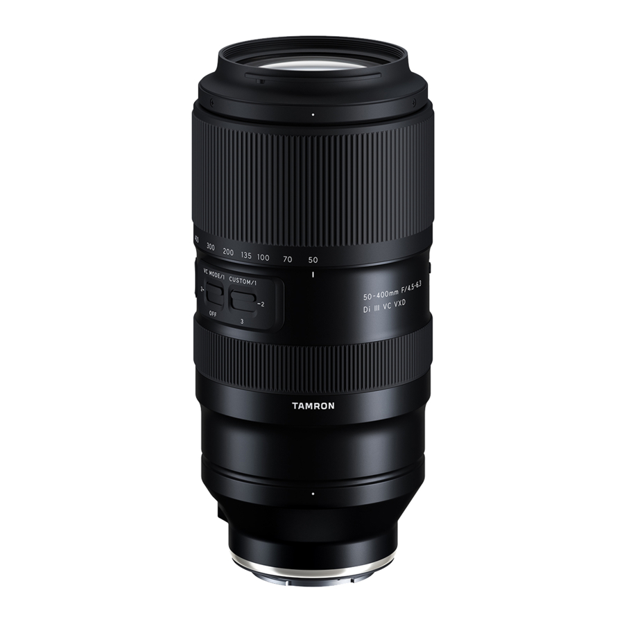
PART NAMES

Fig. 1
- Lens hood
- Hood attaching alignment mark
- Hood locking mark
- Filter ring
- Hood release mark
- Zoom ring
- Focal length scale
- Focal length mark
- Tripod mount mark
- Focus set button
- VC (Vibration Compensation)
switch (For Sony E) / AF/MF switch (For Nikon Z) - Custom switch
- Focus ring*
- Zoom lock switch
- Connector port
- Lens attachment mark
- Lens-camera interface contacts
* Corresponds to the control ring on Nikon Z mounts.
Tripod mount (Model A035TM / sold separately)
- Tripod mount
- Tripod mount locking screw
- Screw hole for safety lock screw
- Safety lock screw (×2)
- Hexagonal wrench
 Before using the lens, make sure to remove the tape on lens surface.
MAIN SPECIFICATIONS
| Model | A067 |
| Focal Length | 50 - 400 mm |
| Maximum Aperture | F/4.5 - 6.3 |
| Angle of View (diagonal) | 46°48' - 6°11' |
| Optical Construction | 18/24 |
| Minimum Object Distance (MOD) | 0.25 m (9.8") (Wide) / 1.5 m (59.1") (Tele) |
| Maximum Magnification Ratio | 1:2 (Wide MOD) / 1:4 (Tele MOD) |
| Filter Size | ø 67 mm |
| Length | 183.4mm (7.2") / Sony E, 185.8mm (7.3") / Nikon Z |
| Maximum Diameter | ø 88.5 mm |
| Weight | 1,155 g (40.7 oz) / Sony E, 1,180 g (41.6 oz) / Nikon Z |
| Lens Hood | HA067 |
| Connector Type | USB Type-C |
- Length: From front end of the lens to mount surface.
- Specifications, appearance, functionality, etc., are subject to change without prior notice.
ATTACHING AND REMOVING THE LENS
Remove the rear cap of the lens. Align the lens attachment mark 16 and mounting mark on the camera, and then insert the lens.
Turn the lens clockwise for Sony E mounts or counterclockwise for Nikon Z mounts until it locks.
To remove the lens, turn the lens in the opposite direction while pressing the lens release button on the camera.
Turn off the power of the camera before attaching or removing the lens.
 For details, please read the instruction manual of your camera.
SWITCHING FOCUS MODE
(Ref. Figs. 1, 2', 3')
For Sony E

Select the desired focus mode on the camera.
For manual focusing, turn the focus ring 13 to acquire the desired focus.
For Nikon Z: AF/MF Switching
(Ref. Figs. 1, 2', 3')

To shoot using autofocus (AF), set both the camera and the AF/MF switch 11 on the lens to "AF". (Ref. Fig. 2') (If the lens is set at "MF", it will not autofocus.)
To shoot using manual focus (MF), set the camera and/or the lens AF/MF switch 11 to "MF". For manual focus, turn the focus ring 13 to acquire the focus. (Ref. Figs. 1, 3')
- Under AF mode, there may be difficulty for autofocus to work depending on the subject.
- For Nikon Z, under the AF mode setting, the focus ring 13 will act as "Control Ring" and can apply functions from the camera.
For details, please read the instruction manual of your camera.
FOCUS SET BUTTON
(Ref. Fig. 1)
Press the focus set button 10 to use the function that has been assigned from the camera.
See the manual of the camera for more details.
For details, please read the instruction manual of your camera.
CONNECTOR PORT
(Ref. Fig. 1)
Lenses with the connector port 15 can be connected to a computer using the TAMRON connection cable (sold separately). Then, using the dedicated "TAMRON Lens Utility TM" application, you will be able to update the firmware and register functions to the custom switch 12.
See the online help of "TAMRON Lens Utility" using the link below for more details.
https://www.tamron.com/jp/consumer/support/help/lensutility/en/
- Do not use the TAMRON connection cable (sold separately) for any purpose other than connecting the TAMRON lens equipped with a connector port to a computer.
- Tamron will not bear any responsibility for any loss or damage of data in use of the TAMRON connection cable (sold separately).
CUSTOM SWITCH
(Ref. Fig. 1)
Using the custom switch 12, you can switch the functions registered to the lens with the dedicated "TAMRON Lens Utility" application.
VIBRATION COMPENSATION
(Ref. Figs. 1 - 3)
For Sony E
To compensate for the vibrations, set the VC (Vibration Compensation) switch 11 to MODE 1 or MODE 2. (Ref. Fig. 2)
Switching the modes
(Ref. Fig. 3)
You can switch the modes by using the VC switch 11.
MODE 1 Basic vibration compensation mode
MODE 2 Panning mode
* MODE 1 does not support panning.
When MODE 1 or MODE 2 is set, the viewfinder image may become blurred immediately after the shutter button is pressed halfway. This is due to the principles of the vibration compensation mechanism and not a malfunction.
For Nikon Z
For vibration compensation, the lens do not have a switch for vibration compensation, please activate the function from the camera body.
Vibration compensation is effective under the following conditions
- Dimly lit locations
- Locations where flash photography is prohibited
- Locations where tripod cannot be used
Vibrations may not be compensated sufficiently under the following conditions
- When a photograph is taken from a vehicle that is shaking greatly
- Shooting during excessive movement of the camera
- When shooting while using a tripod
- You may feel the lens rattle when the camera is turned off or when the lens is removed from the camera. This is not a malfunction.
- Set the VC switch 11 to OFF when you are shooting while the camera is secured by something other than your hand (such as a tripod).
Set the VC switch 11 to OFF when taking pictures with bulb photography (long exposures). Otherwise, vibration compensation may cause a malfunction. (For Nikon Z, the lens do not have a switch for vibration compensation, please activate the function from the camera body)
For details, please read the instruction manual of your camera.
ZOOMING
(Ref. Fig. 1)
Turn the zoom ring 6 to adjust the focal length (Zoom position) to a desired position.
ZOOM LOCK
(Ref. Figs. 1, 4, 5)
You can lock the zoom ring 6 at a focal length of 50 mm to keep it from rotating.
Setting the zoom lock
(Ref. Fig. 4)

Align 50 mm on the focal length scale 7 with the focal length mark 8.
Set the zoom lock switch 14 toward the subject
Releasing the zoom lock
(Ref. Fig. 5)

Set the zoom lock switch 14 toward the camera.
To zoom, release the lock, and then rotate the zoom ring 6.
LENS HOOD
(Ref. Figs. 1, 6, 7)
The hood 1 can eliminate stray light that may affect the picture.
Using the lens hood
(Ref. Fig. 6)

Align the hood attaching alignment mark 2 of the hood with the hood release mark 5 of the lens.
Rotate the hood 1 in the direction of the arrow until the hood locking mark 3 meets the hood release mark 5.
Stowing the lens hood
(Ref. Fig. 7)

Attach the hood 1 in reverse and rotate it until it locks.
Be aware that the periphery of the photographed image may be darkened if the hood 1 is not attached properly.
TRIPOD MOUNT
(Sold separately)
(Ref. Figs. 1, 8 -10 )
You can secure the lens to the tripod using the separately sold tripod mount 18 (Model A035TM).
Attaching and removing the tripod mount
(Ref. Figs. 8, 10)

You can attach and remove the tripod mount by loosening tripod mount locking screw 19 and then lift the portion with the screw, to open the ring.
When attaching the tripod mount, make sure that the protruding part on the inner side of the tripod mount is inserted into the groove on the lens barrel, and then tightly secure the tripod mount locking screw 19.
If this protruding part is not inserted into the groove when the tripod mount is attached, the lens barrel may be damaged and the lens may fall off.
Changing the directional position of the camera
(Ref. Fig. 9)

When you change the directional position of the camera, you can rotate the lens by loosening the tripod mount locking screw 19.
Align the tripod mount mark on the lens 9 with the mark on the tripod mount 10.
After determining the shooting position, tightly secure the tripod mount locking screw 19 to fix the position.
The tripod mount 18 can be attached to an ARCA-SWISS camera platform.
SAFETY LOCK SCREW (Accessory for the tripod mount)
(Ref. Figs. 1, 11)
We recommend attaching the lock screws in accordance with the camera platform type when you use an ARCA-SWISS-standard compatible camera platform or clamp.
- How to use safety lock screws (Ref. Fig. 11)
![]()
The safety lock screws 21 prevent the lens/camera from falling from the camera platform when a tripod mount is attached to an ARCA-SWISS-standard compatible camera platform or clamp.
As shown on the figure, use the hexagonal wrench 22 to tighten the safety lock screws 21 to the two screw holes 20.

After attaching the safety lock screws 21, the screw heads protrude from the tripod mount bottom surface to prevent the lens/camera from falling. For this reason, if you are using a camera platform or a clamp other than ARCA- SWISS-standard compatible, you do not need to have them attached.
USAGE PRECAUTIONS
- An internal focusing (IF) system is employed to reduce the minimum focus distance. The angle of view may be wider than that of lenses with other focusing systems when shooting at a distance less than infinity.
- The lens hood or the lens barrel may block the light from the flash. It is recommended to perform trial shooting in advance.
- Differences in the display systems of cameras may cause to show values different from the maximum and minimum aperture values from the specifications. This is not an indication of an error.
- Do not touch the lens-camera interface contacts 17 with your fingers. Otherwise, it may cause a malfunction.
- If the temperature changes suddenly, condensation may form and cause malfunctions.
- The front lens is covered with stain-proof coating. After removing the dust on the lens surface with a blower or another means, wipe it with a dry cloth.
- Never use benzene, thinner, or other organic solvents to clean the lens.
- Store the lens in a clean and well-ventilated place.
- For more details on the lens cleaning and storage, the compatibility with cameras, and other support information see our website. https://www.tamron.com/global/consumer/support/
Precautions for Safe Use of Tamron Lenses
For safe operation be sure to carefully read this "Precautions for Safe Use of Tamron Lenses" and the manual before using the product.
After reading them, store them in a place where they can easily be reviewed whenever needed.
Caution instructions are divided into the following two categories according to the degree of danger involved.

This indicates instructions which if not followed or if performed incorrectly could lead to death or serious injury.
- Do not view the sun or other strong light source directly through the lens or through a camera while using this lens. Doing so could cause loss of vision, damage to the lens and/or the camera, and possibly cause the lens and/or camera to ignite.
- Do not dissemble, repair, or modify the lens. This could damage the lens or camera.
- Keep the lens out of the reach of small children. There is a risk of injury if the lens is dropped or falls down.

This indicates instructions which if not heeded or if performed incorrectly could lead to bodily injury or physical damage
- Do not place lens in direct sunlight or leave it in an extremely hot place such as inside a car. Doing such could damage the internal parts of the lens or cause a fire.
- Always attach the lens cap whenever the lens is not in use.
- When attaching the lens to the camera, ensure that the lens has been properly attached to the camera and firmly locked. If the lens is not attached properly, it could be difficult to remove or it could fall off causing damage or injury.
- Do not use this lens for any application other than photography.
- Do not carry around the lens while it is still attached to a tripod.
- Regarding the lens equipped with a connector port
- Place the lens in a stable location when customizing the lens using the dedicated application (TAMRON Lens UtilityTM). Make sure not to let it fall or impact the lens.
- When connecting the lens to a computer, use a Tamron connection cable (sold separately).
- Do not touch the connector port with your fingers or a metal object. Also, prevent dust or water from adhering to the connector port. If the connector port is dirty, it may cause connection problems.
- Tamron will not be responsible for damages caused by a failure, a fire, or other accidents that may occur when using an accessory other than Tamron accessories. Note that in case of such damage, repair of the Tamron lens will be charged since it is not covered by the warranty.
Documents / Resources
References
Download manual
Here you can download full pdf version of manual, it may contain additional safety instructions, warranty information, FCC rules, etc.
Download Tamron 50-400mm F/4.5-6.3 Di III VC VXD, A067 Manual
Advertisement


Need help?
Do you have a question about the 50-400mm F/4.5-6.3 Di III VC VXD and is the answer not in the manual?
Questions and answers