Table of Contents
Advertisement
Quick Links
USER
MANUAL
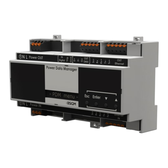
PDM-Power and Data
Manager
Document Revision D | Released 2024-10-23
This edition applies to firmware version 2.00 or later
This manual covers installation, use, and maintenance of the SGM Power and Data Manager. A digital
version is available at www.sgmlighting.com or upon request via support@sgmlighting.com. The informa-
tion in this document is subject to change without notice. SGM and all affiliated companies disclaim liabil-
ity for any injury, damage, direct or indirect loss, consequential or economic loss, or any other loss occa-
sioned by the use of, inability to use, or reliance on the information contained in this manual. The SGM logo,
the SGM name, and all other trademarks in this document pertaining to SGM services or SGM products are
trademarks owned or licensed by SGM, its affiliates, and subsidiaries.
English edition © 2024 SGM Lighting ApS.
Advertisement
Table of Contents

Related Manuals for SGM PDM


Summary of Contents for SGM PDM
- Page 1 The SGM logo, the SGM name, and all other trademarks in this document pertaining to SGM services or SGM products are trademarks owned or licensed by SGM, its affiliates, and subsidiaries.
-
Page 2: Dimensions
DIMENSIONS Power out 3,543in 90mm Power in 6,260in 159mm 2,283in 58mm 2,283in 58mm 3,543in 90mm All dimensions in millimeters and inches. Drawing not to scale Revision D | Released 2024-10-23... -
Page 3: Table Of Contents
11 Information panel (H) 11 Warning Indicator 12 CONFIGURATION 12 Setting universe and address 12 CONTROL MENU 13 DMX Chart 13 SGM Network admin interface (SNA) 14 RDM 14 Sensors 14 PID Commands 14 PDM DEFAULT SETTINGS 15 MAINTENANCE 15 Firmware updates... -
Page 4: Safety Information
WARNING! READ THE FOLLOWING SAFETY PRECAUTIONS CAREFULLY BE- FORE UNPACKING, INSTALLING, POWERING OR OPERATING THE DEVICE. SGM devices are intended for professional use only. They are not suitable for household use. Les dispositifs SGM sont impropre à l’usage domestique. Uniquement à usage professionnel. -
Page 5: Before Installing This Product
∙ Do not mount near gas or electric heaters. ∙ Mount the PDM only in locations and at heights where it will not be readily subjected to tampering by unauthorized personnel e.g. electrical cabinets or similar. ∙ The use of accessory equipment not recommended by the manufacturer may cause an unsafe condition. -
Page 6: Overview
∙ PDM is running and mains power output is on. If inrush temperature gets above 120 degrees Celsius a hardware fail is suspected. Mains output power is automatically turned off and “HI TEMP” is displayed. This state can only be reset by power cycling the PDM. -
Page 7: Cabling And Termination
CABLING AND TERMINATION Install the PDM in a location where it will not be subject to tampering or vandalism and at ambient temperatures between -20° C to +50° C (-4°F–122°F), 5–95% non-condensing relative humidity. Power and data lines are connected as follows:... - Page 8 Inrush control and DMX node: PDM used as an inrush current limiter and as an DMX node converting the incoming Art-Net/sACN signal to wired DMX. The fixture leader cable is connected to the DMX output of the PDM. Neutral Live...
-
Page 9: Power
The Power & Data Manager can increase the number of fixtures connected to a standard breaker by actively man- aging and controlling inrush power. PLEASE NOTE: THE PDM IS NOT AN OVERCURRENT PROTECTION DEVICE. ALL PDMS AND THE FIXTURES CON- NECTED DOWNSTREAM MUST BE PROTECTED BY OVERCURRENT PROTECTION SUPPLIED AND INSTALLED BY A QUALIFIED LOCAL ELECTRICAL AUTHORITY. -
Page 10: User Interface
DISPLAY The PDM can be set up by using the control panel and on-device display or through RDM. The display shows the current status and menus of the PDM. Before turning on the PDM, make sure that cables and wires are properly connected. -
Page 11: Display
Displays the Art-Net/sACN universe of the PDM as a 1 channel fixture. The universe can be changed directly from this view. DMX ADDRESS (C) Displays the DMX address of the PDM as a 1 channel fixture. The universe can be changed directly from this view. WIRELESS INDICATOR (D) Signal strength of a connected wireless transmitter is displayed EXTERNAL DATA PROTOCOL (E) Shows the external data protocol. -
Page 12: Configuration
SETTING UNIVERSE AND ADDRESS The PDM 1 channel fixture universe and address are shown on root screen of the display. To change the universe and address, start by pressing the up or down button once. Use the up and down button to first change the universe. -
Page 13: Dmx Chart
200-205 OFF, 210-215 ON SGM NETWORK ADMIN INTERFACE (SNA) The PC application – SNA is primarily used when the PDM is used as Inrush limiter for a VPL setup. From the SNA it is possible to : ∙ monitor temperatures and mains relay state. -
Page 14: Rdm
Slot Info 0x0121 Slot Description 0x8060 Serial Number 0x8649 GET / SET Output Universe PDM DEFAULT SETTINGS • Turn off display after one minute • 1 ch. Fixture DMX ADR 1 • Display Normal orientation • 1 ch. Fixture Universe 0 •... -
Page 15: Maintenance
PDM - Power & Data Manager ........ -
Page 16: Support Hotline
SUPPORT HOTLINE SGM offers 24/7 technical support. Worldwide: https://sgmlight.com/contact/sgm-hq-dk https://sgmlight.com/contact/sgm-n-america support@sgmlighting.com APPROVALS AND CERTIFICATIONS Conforms to ..............2014/35/EU: Low Voltage Directive Conforms to . -
Page 17: User Notes
USER NOTES Revision D | Released 2024-10-23... - Page 18 SGM LIGHTING APS Sommervej 23 8210 Aarhus V Denmark Tel: +45 70 20 74 00 info@sgmlighting.com www.sgmlighting.com...
Need help?
Do you have a question about the PDM and is the answer not in the manual?
Questions and answers