
Subscribe to Our Youtube Channel
Related Manuals for Roga M14


Summary of Contents for Roga M14
- Page 1 Instruction Manual Vibration Monitor valid from version 00x.011 ROGA Instruments Im Hasenacker 56 56412 Nentershausen Tel. +49 (0) 6485 - 88 15 803 Fax +49 (0) 6485 - 88 18 373 Email: info@roga-instruments.com Internet: https://roga-instruments.com...
- Page 2 Contents 1. An Introduction to Controls and Indicators ............1 2. Purpose ........................2 Measuring quantities ............... 2 Interfaces ..................2 Outputs .................... 2 Indicators ..................2 3. Function ........................3 Sensor Input ..................3 Transducer Sensitivity ..............3 Amplifier ..................3 Filter ....................
- Page 3 6.2.2 Settings Menu ..................16 USB connection................17 RS-485 connection ................ 17 Instrument Data ................17 Saving and Loading Settings ............17 Standard Settings ................17 6.2.3 Sensor Settings ..................18 IEPE Supply .................. 18 Sensitivity ..................18 6.2.4 Gain ......................18 6.2.5 Filter and Integration ................
- Page 4 Relay Settings ................29 Sensor Sensitivity ................30 IEPE Supply .................. 30 Warning Limit ................30 Read Settings ................. 30 MODBUS Address (RS-485) ............31 Detection ..................31 9.3 RS-485 Communication in ASCII Mode ............31 9.4 MODBUS RTU ..................... 33 10.
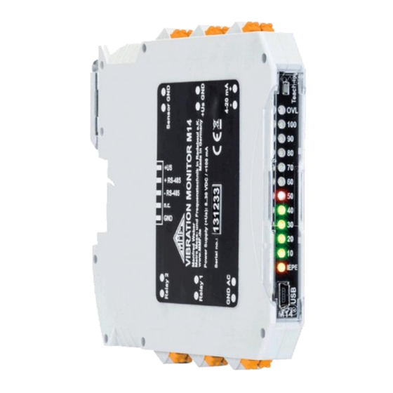
- Page 5 1. An Introduction to Controls and Indicators Figure 1: Front view Figure 2: Back view Figure 3: Connectors...
- Page 6 2. Purpose The M14 is suitable for versatile tasks in the field of vibration measurement and monitoring. Typical applications include monitoring the smooth running of rotating machines to DIN/ ISO 20816 and monitoring rolling bearings. The M14 enables maintenance technicians to recognize the early signs of wear and prevent consequential damages.
- Page 7 IP67. The constant current which powers the sensor electronics is provided by the M14 and can be switched off via the inter- faces if required. This can be useful, for example, when two M14 are run with one sensor. In this case, the sensor should only be supplied by one of the two instruments.
- Page 8 These states are detected from the sensor bias voltage at the input. The valid range is between 1 and 20 V. Power Supply To operate the M14 requires a DC voltage between 8 and 30 V. The current consumption is below 100 mA. The higher the supply voltage, the lower the current.
- Page 9 4. Installation 4.1 Selecting the Measuring Points Sensor Before putting the instrument into operation, suitable measur- Attachment ing points on the machine must be found. For this it is advis- able to call upon personnel with experience in machine moni- toring.
- Page 10 DIN/ISO 20816-1 The standard DIN/ISO 20816-1 recommends bearing hous- ings or their immediate surrounding as preferable measuring points for machine vibration (figure 5 to 8). For routine monitoring it is often sufficient to measure either in the vertical or horizontal direction. In the case of machines with horizontal shafts and rigid foundations, greater vibration amplitudes occur horizontally.
- Page 11 Figure 7: Measuring points on electric motors Figure 8: Measuring points on reciprocating machines 4.2 Attachment The M14 is designed for attaching to a 35 mm DIN rail, which needs to be mounted horizontally. The instrument should be installed in a dust-free moisture-proof environment, preferably in a switch cabinet.
- Page 12 9). The image shows a DIN-rail with bus connectors for RS- Bus Connectors 485 and supply voltage. The bus connectors M14-BUS (Fig- ure 11) are slotted into each other sideways and clipped on to the DIN-rail. When locked in place all the supply voltage...
- Page 13 (see section 4.2 ), the supply terminals remain uncon- nected. Sensor Input The M14 is suitable for connection with all types of ac- celerometers to IEPE standards. The built-in constant current source for the sensor electronics delivers approximately 4 mA.
- Page 14 Relay Outputs The M14 has two relay outputs, which are usually used for pre- alarms (warning) or the main alarm. The M14 uses solid- state PhotoMOS relays with a switching capacity of 60 V AC and 0.5 A.
- Page 15 Figure 13: 4-20 mA Loop The voltage at the terminals +I and -I must not exceed 30 V. AC Signal The signal output provides the amplified, unfiltered sensor Output signal. It can be used for connecting data loggers and analyzers or for function tests.
- Page 16 Additional measuring instruments can also be powered from the current loop, as long as the loop supply voltage is high enough to guarantee the minimal voltage drop of 8 V. The 24 V-supply voltage of the M14 can also be used to power the loop.
- Page 17 Figure 14: Current loop instrument M12-DIS If desired LED background lighting can be switched on. This requires a separate DC voltage UBLBL, which is applied via a series resistor RBL on the BL+ and BL- terminals. The cur- rent requirement is 30 mA. The series resistor is calculated as follows: - 5 V 30 mA...
- Page 18 Panel thickness 1 to 3 mm Panel cut out 62 mm x 32 mm Bracket Mounting bezel Figure 15: Panel cut out Insulating Shake-proof washers washers Figure 16: Display mounting If not otherwise specified when ordering, the M12DIS is sup- plied with a factory calibration to display “0”...
- Page 19 M14 a vibration reference signal isfed into the accelerometer or a generator signal is applied to the M14 input, as explained in chapter 10. Preferably a vibra- tion calibrator should be used to eliminate errors by calibrat- ing the entire measuring chain.
- Page 20 The driver installs a virtual COM port on your PC and works in CDC mode, which allows simple control using the ASCII- commands. Once you have installed the driver the M14 will be recog- nized by the system. PC Software...
- Page 21 USB connection In the upper area of the window you will find all details of the connected instrument. Click “USB” and select the number of the virtual COM port which was assigned to the M14 device. Now the settings from the M14 will be transferred to the PC software. RS-485...
- Page 22 A steady connection to M14 is indicated by the green framed “OK”. If the instrument fails to be recognized (“ERROR”), click “search” to restart the search. In this case it may be nec- essary to briefly unplug the USB cable.
- Page 23 6.2.3 Sensor Settings IEPE Supply The M14 is designed for connection with an IEPE compatible accelerometer. In Figure 1 on page 3 you will find the con- nection terminals for the sensor. An IEPE sensor requires a constant current source for supplying the sensor electronics. The constant current can be switched off if not needed (Figure 19).
- Page 24 (“n.c.”, normally closed) when the alarm is signaled. Selecting “n.c.” enables a self-monitoring function Delays of the M14 supply voltage, as well as the relay cabling, This happens because in both cases the relay circuit opens when interrupted, thereby signaling an alarm.
- Page 25 Values The M14 relay output can be set for response times in the range of some milliseconds after tripping the alarm limit. In this mode the instantaneous value of the vibration is moni- tored instead of RMS or peak values.
- Page 26 est response times it is recommended to use fixed gain instead of auto-ranging (see page 19). At overload of the signal path (LED “OVL”) and error in the Relay at sensor circuit (LED “IEPE”) both relay outputs switch to alarm Overload and status.
- Page 27 Monitoring mode peak” or “FFT” in the PC soft- ware. The selected mode remains active when the USB cable is unplugged from the M14 or when it is disconnected or re- connected to the power supply. 7. Measuring Functions 7.1 Measuring RMS and Peak Values...
- Page 28 In the upper section of the measuring window you can see the Measuring RMS current RMS and peak values. With a high pass frequency of and Peak Values 0.3 Hz a measurement value is recorded every 2.8 seconds, and with all other high pass frequencies every 1.4 seconds. At overload, “OVER”...
- Page 29 The tenth amplitude applies until the upper limit frequency. You can hide and show the limit value line on the diagram, without it having any influence on the M14. This compares the spectral lines in FFT monitoring mode with the limit value belonging to each frequency.
- Page 30 Ex - cel diagram. 8. Teach-in-Function for Alarm Limits With the help of the teach-in function the M14 can determine the alarm limit automatically on the basis of the currently pending vibrations.
- Page 31 As a basis for integration into LabView we provide the project data for the setup and measurement program (see sec- tion 6.2 ). As a template for PLC applications the WAGO project data m14.ecp is available on demand. 9.2 USB Communication in CDC Mode Commands The commands and the answers are ASCII strings.
- Page 32 #Fhhlli: Filter for RMS and peak measurement Filter and h: high pass filter index (2 digits), Integrator at acceleration: 00 = high pass off or FFT; 01 = 5 Hz; 02 = 10 Hz; 03 = 20 Hz; 04 = 50 Hz; 05 = 100 Hz; 06 = 200 Hz;...
- Page 33 Alarm Threshold #Lmxxxx.x: Set alarm threshold m: r = RMS; p = peak x: alarm threshold; 5 digits; 0.1 to 6000.0; with decimal point before the last digit E.g.: #Lr0012.0 (RMS, 12.0 m/s²) Read RMS and #M: Fetch RMS and peak Peak Values Return: rrrrr.r ppppp.p...
- Page 34 #Onfffffaaaa.a: limit values for FFT monitoring FFT Limit n: limit value number (0 to 9, 1 digit), Values f: frequency in Hz (5 digits), a: Amplitude in m/s² (5 digits with decimal point before last) example: #2015000010.0 (limit 2 at 1500 Hz 10,0 m/s²) The frequencies have to be entered in numerical sequence (the lowest first).
- Page 35 % of the alarm limit (10 – 90 %), 2 digits Read Settings #X: Read instruments data and settings Answer: tttt Ver. sss.hhh Ser. xxxxxx t: Type code (M14 , 4 characters) s: software version (3 digits) h: hardware version (3 digits) x: serial no. (6 digits)
- Page 36 a: FFT limit value 1 (5 digits, decimal point before last) O9: fffff aaaa.a S: sssss s: sensor sensitivity, 4 digits and decimal point...
- Page 37 By the USB command #Y000 or by entering “000” in “MODBUS address” of the setup program (Figure 30) the RS- 485 interface of the M14 is set to ASCII command mode. Thus the described set of USB commands becomes available via the RS-485 interface.
- Page 38 Figure 30: RS-485 settings in the setup program...
- Page 39 8 data bits, 1 stop bit, no parity. With the MODBUS RTU communication protocol, several M14 modules can be set and read out by a client, e.g. a PC or a PLC. Data is transmitted in binary format. All measured values and limit values are coded as 32-bit floating point numbers (float or single) in accordance with IEEE 754.
- Page 40 R: RMS as float (32 Bit) P: Peak as float (32 Bit) The peak value is the highest measured value since the last polling. If the M14 is in FFT mode, exception code 0x06 is returned. 0x10 .. 0x19: Read FFT in blocks Address...
- Page 41 0x10 0x00 0x30 0x00 0x02 This command uses the address 0 (broadcast) and is aimed at all M14 units. Each device address must only exist once on the bus. g: MODBUS address (1 .. 247) s: M14 serial number (000001 .. 999999)
- Page 42 0x14 n: device name (20 characters) Note: Active communication between an M14 and the MODBUS client can be rec - ognized by the flashing “OVL” LED. It flashes for each data packet sent by the M14. Note: At https://mmf.de/en/produkt/m14/ you will find a sample PLC application featuring all MODBUS RTU setup and measurement functions of the M14 (Figure 32).
- Page 43 10. Calibration Re-Calibration The M14 is factory calibrated so that after entering the cor- rect sensor sensitivity (see section 6.2.3 ) you can accurately measure amplitudes. Vibration The calibration can be carried out in a simply way with a vi- bration calibrator of the ‘VC’...
- Page 44 12. Measuring Machine Vibration The stationary monitoring of machine vibration as part of predictive maintenance can have a significant impact on cost reduction and avoid unexpected breakdowns. The evaluation of machine vibration requires a certain degree of experience. At this point we can only enter the subject briefly.
- Page 45 12.2 Monitoring Roller Bearings While the procedure shown in in section 12.1 to DIN/ISO 20816 deals with vibration, arising due to unbalance, this sec- tion concerns vibration of rolling bearings. Typical causes of damage to roller bearings are fatigue, corro- sion, cage damage, poor lubrication, wear due to too high de- mands.
- Page 46 The following table shows the crest factor and alternatively the product of peak and RMS in relation to the degree of damage. â/a â · a Condition â No damage small small small Minimal single damage small increased >3 slight increase Several small single damages increased increased...
- Page 47 13. Technical Data Measuring Range (1/10 mV/ms sensit.) peak vibration acceleration 7000 / 700 m/s² 10000 / 1000 m/s² 10000 / 1000 mm/s vibration velocity 7000 / 700 mm/s Measuring Error (10 mV/ms sensitivity) peak 3 % at >0.1 m/s² ...
- Page 48 output at overload and sensor error: 24 mA...
- Page 49 AC Output acceleration signal; û = ± 3 V; sensitivity: 0.4 · Gain; 1 Hz to > 100 kHz; impedance 100 Sensor Monitoring IEPE LED at <1 V and >20 V bias voltage; at sensor error 24 mA at 4-20 mA loop and alarm relay set Overload Indicator OVL LED, threshold at...
- Page 50 According to EMC Directive 2014/30/EC and UK Electromagnetic Compatibility Regulations 2016 Product: Vibration Monitor Type: M14 It is hereby certified that the above mentioned product complies with the demands pursuant to the following standards: DIN / BS EN 61326-1: 2013...
Need help?
Do you have a question about the M14 and is the answer not in the manual?
Questions and answers