Advertisement
Quick Links
Installation
Guide
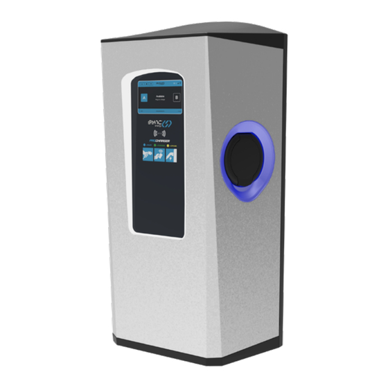
2 X 7.4KW DUAL W ALL CHARGER:
EVPCWSM27BGR
EVPCWSM27BGRP
click to navigate directly to the page
Introduction / Box contents
Commercial Installation & Commissioning
Stage 2 (User app setup)
Single Phase Pro Charger Range
(WI-FI / LAN / 4G / RFID)
(WI-FI / LAN / 4G / RFID / Payment T erminal)
Contents
Safety information
Installation & testing
Troubleshooting
Domestic Commissioning
Stage 1 (Installer app)
Domestic Commissioning
T echnical
www.sync.energy
Return to Contents
Advertisement

Subscribe to Our Youtube Channel
Related Manuals for SYNC PROCHARGER EVPCWSM27BGR


Summary of Contents for SYNC PROCHARGER EVPCWSM27BGR
- Page 1 Introduction / Box contents Safety information Installation & testing Troubleshooting Commercial Installation & Commissioning Domestic Commissioning Stage 1 (Installer app) Domestic Commissioning Stage 2 (User app setup) T echnical www.sync.energy Single Phase Pro Charger Range Return to Contents...
- Page 2 IP65 to explain basic requirements RATING and options to be considered when installing a Sync Energy charger. The unit is designed for installations inside or outside, the advanced safety technology we have built into the unit ensures its safe usage.
- Page 3 Safety information Warning: The supplied Sync Energy charger is manufactured to be safe without risk provide they are installed correctly, used, and maintained in accordance with the manufacturers recommendations and installed by a competent electrical installer in accordance with national and local regulations and legislation applicable at the time of installation, e.g.
- Page 4 Amendment 2 Wiring Regulations. To conform with BS 7671, on occasions a double pole MCB/RCD or other means of isolation may be required. Important note: A DC Leakage fault in the vehicle may “blind” a type “AC” RCD and render it ineffective, never feed any EVSE From an upstream Type “AC”...
- Page 5 Where certain conditions dictate an earth electrode must be used it shall be independent from the distributors earth system with no direct interconnection (the incoming supply SWA protective earth should be isolated from the housing and/ or earth electrode). The electrical installer shall install a suitable electrode complete with termination housing and covers where appropriate, warning labels should be visible and...
- Page 6 Isolation and switching for safety and maintenance To ensure the EV charger can be “turned off” to enhance security and enable maintenance activities, a double pole isolator (or DP RCD or RCBO) suitably rated must be installed within the customer’s property. Return to Contents...
- Page 7 Installation requirements The EV charger is suitable for installation inside and outside on a solid wall or structure. The installer should consult with the building owner to establish their preferred installation location. This should take into consideration the length of charging cable and risk of vehicle impact etc.
- Page 8 The EV charger is suitable for bottom or rear cable entry, if using rear cable entry ensure the rubber grommet is used to maintain the IP rating. When using Loop In / Loop Out installation method use one of the bottom cable entry points to link to the next charger.
- Page 9 If load balancing is required, a single CT clamps will be required for correct balancing on three phase power. We suggest the use of Sync Energy CT clamps, EV A120CT1 or EV A400CT1 depending on cable incoming size (Not supplied). These should...
- Page 10 • A test to confirm the continuity of the circuit protective conductors • A test to confirm the integrity of the circuit insulation resistance • A test to confirm the polarity of the installation is correct • Where applicable a test to confirm the earth electrode resistance is within acceptable tolerances (or)
- Page 11 Electrical Installation Isolate the power Remove the mounting bracket from the charger Use the bracket as a template for Return to Contents...
- Page 12 If rear cable entry, open the charger front and pre drill the entry port, if bottom entry skip this step Fit the charger to the mounting plate ensuring to use the 2 bottom screws to secure the charger Return to Contents...
- Page 13 If Bottom entry, open the front of the charger and drill to suit cable gland size, if rear entry skip this step Ensure correct polarity when making incoming power connections Return to Contents...
- Page 14 For dynamic load balancing, insert wires into the small connector If using external 485 meter, then dip switch 3 needs to be changed to ‘On’ ‒ 485A ‒ CT– 485B Plug connector into PCB, ensure correct polarity Return to Contents...
- Page 15 Once all connections are done and secure, close the charger cover and tighten fixing screws – ensure the MCB in the charger is turned on Clip the Fascia plate onto the front of the charger, ensure the tabs clip into the body of the charger Return to Contents...
- Page 16 Fit locking screws to secure the cover Return to Contents...
- Page 17 INSTALLER APP – Download the ‘SyncEnergy’ app by clicking this link Also available from the Installer Portal on the sync.energy website, or using the QR code opposite. Intuitive Interface: The revamped interface is designed with the installer in mind. Everything you...
- Page 18 Upon Powering the charger, the status indicator light will show Yellow. This indicates that the charger is ready for network setup but is not yet connect to the internet. These steps are still required for 4G connected versions for setting of Dynamic Load Management.
- Page 19 Ensure Bluetooth is activated on your device, and select set up new product. If the EV charger does not show up under EV Charger option, go back and select show all Bluetooth devices. If no Bluetooth devices are shown, please check Bluetooth is turned on and the permission was granted in the app.
- Page 20 Then enter the password shown on the identification label. A. Full EV Charger Setup allows full set up of Load balancing and other settings. B. Network Set up allows quick Wi-Fi or Lan connection to be changed and set up. Return to Contents...
- Page 21 Charger Server: Select “Monta” – this is the included App. “Ev.Energy” and “SyncEV” are alternative options (additional costs may be incurred). “Manual” can be used for other alternative back offices. If unsure, Choose “monta”. Charger Mode: “APP” for smart charging via the consumer App (see next page);...
- Page 22 Indicator Brightness: Adjust from 1 to 100% to change the brightness of the status indicator. Local Charger Settings: Offline charging is enabled as default, for commercial paid charging we recommend this is disabled. This controls if the charger will allow a charge to start while not connected to the back office system.
- Page 23 Dynamic Load Management: If Dynamic Load management or Integrated SolarCharge is required, then toggle right. If the charger is been used in the Master/ Slave load management configuration turn on Secondary Device to enable the charge point to be Slave unit, by default when turned off it will be Master unit.
- Page 24 Balancer: This should be enabled if using the Balancer Multi-Charger hub, and then the correct phase rotation enabled. Circuit limits are set on the balancer unit only. Press Save and Proceed to save these settings. Check the shown electrical measurements match the measured readings.
- Page 25 Screen Configurations can be managed here such as - Screen PIN set as a 4 digit number, Screen saver time (in seconds) determine the amount of stand by time before the screen returns to the default screen saver time, check the time and date matches before pressing save and proceed.
- Page 26 For Wi-Fi, select the SSID network name and enter password. For LAN, ensure that “Manually Set Static IP Address” is disabled (unless advanced settings are required). For 4G, the settings will have been pre- configured where supported. Multiple options can be selected if required, this will allow a fall-back, e.g from Wi-Fi to 4G if fitted in case of network loss.
- Page 27 On LAN, the charger will default to DHCP. If static IP is required for the network connection, set the option “manually Set Static IP Address” to On and a manual IP address can be entered. Press Save and Proceed to start network connection.
- Page 28 If unable to establish network connection call 01952 983 940 or email: support@sync.energy Note: The network connection from the device to the Internet is fully encrypted and secure. Additionally, no user data is stored on the charger. Return to Contents...
- Page 29 Domestic Commissioning Stage 2 of 2 Download the Monta smart app: Apple app store click here Google play store click here or search for ‘Monta EV charging’ on Apple app store or Google Play STEP 3 STEP 3 Using your smart-phone scan the unique Monta QR Code on the ‘Quick Start Guide’...
- Page 30 Create an account using your customers phone number or social logins (Apple/Google/Microsoft) STEP 5 FOLLOW THE STEPS TO CONNECT YOUR CHARGE POINT TO MONTA Name your charge point and set the location. Connect the EV charger to Monta – select the socket outlet, name the charge-point and set the location 05/05/202...
- Page 31 Monta to start charging Need help with the app? Contact Monta customer support through the app or via the website Monta.com Need help with the charge-point? Contact Sync Energy technical support at: support@sync.energy or via the website at www.sync.energy Return to Contents...
- Page 32 CONNECT Install the charge-points CONFIGURE Set the configurations in the Sync Energy installer app and connect all chargers to the internet COMPLETE Pass the charger details to the charge-point owner How it works: To streamline the process, email us...
- Page 33 • Model and charger ID (for every charger in the installation) • Payment Terminal SN/s (Where Applicable) • Contact details for the charge-point owner: • Company name • Name of charge-point manager • Site address • T elephone number for charge-point manager •...
- Page 34 5 years from date of delivery: products will be repaired or (at Sync Energy’s discretion) replacements will be supplied or (at Sync Energy’s discretion) a credit note will be issued. This guarantee is subject to Sync Energy’s...
- Page 35 Notification of any defect is given to Sync Energy as soon as reasonably practicable after becoming apparent, and the products then returned to Sync Energy. The products have only been operated under normal operating conditions and have only been subject to normal use.
- Page 36 T echnical data PART NO: EVPCWSM27BGR Wall Mounted with 4G, MID Meter - Single Phase EVPCWSM27BGRP Wall Mounted with 4G, MID Meter & Payment T erminal - Single Phase SOCKET TYPE: Type 2 with Autolock MAX OUTPUT: 2 x 7.4kW or 1 x 7.4kW / 2 x 3.6kW, MAX INPUT: 100A, 230-240V TO SPECIFY:...
- Page 37 333mm 210mm Electrical Specifications SUPPORTS DAISY Yes, up to 35mm cable CHAIN INSTALL: INPUT CABLE 35mm MAX SIZE: MAX INPUT (A): 100A INTERNAL 80A - Single Phase, 2x40A OVERCURRENT - Single Phase RA TING (A): INPUT VOL TAGE: 220-240V (Single Phase) INPUT FREQUENCY: 50-60hz PEN FAUL T:...
- Page 38 ANTI TAMPER 2 Layer Protection built in DETECTION: OVER VOL TAGE: Built In Operating Conditions & Construction STORAGE: -30 to 55°C OPERATING: -25 to 40°C RELATIVE 5-95% HUMIDITY: IP RA TING: IP65 IK RATING: IK10 Body, IK08 Screen POWER 8W Standby DISSIPA TION: MOUNTING: Wall Mounted, Multiple wall fixing...
- Page 39 Screen layout Back Return to home Connectivity status Settings Time Firmware version Charger ID Socket A Socket B Return to Contents...
- Page 40 Troubleshooting For further information, or to refer to our FAQs, please visit our website: www.sync.energy The status of the EV charger can be identified by referencing the colour shown on the LED indicator: • Solid Blue – Standby – Charger has power and is connected to the network.
- Page 41 Need help with the charge-point? Contact Sync Energy technical support at: support@sync.energy or via the website at www.sync.energy Sync Energy is a trading name of Luceco PLC Luceco PLC Stafford Park 1, T elford, TF3 3BD, England (EU) Luceco SE...
Need help?
Do you have a question about the PROCHARGER EVPCWSM27BGR and is the answer not in the manual?
Questions and answers