
Related Manuals for Daikin RXT09AVJU9


Summary of Contents for Daikin RXT09AVJU9
- Page 1 DAIKIN ROOM AIR CONDITIONER INSTALLATION MANUAL R32 Split Series Installation manual Manuel d’installation Manual de instalación MODELS RXT09AVJU9 RXT12AVJU9...
- Page 2 Contents 3. Flaring the pipe end ............. 7 Safety Considerations ........1 4. Refrigerant piping ............8 Accessories ............. 3 5. Pressure test and evacuating system ......9 Precautions for Selecting a Location ... 3 Wiring ............... 10 Precautions on Installation ......4 Facility Setting (cooling at low outdoor temperature) ...
- Page 3 Corroding copper pipes or soldered parts may result in is shorted and operated forcibly, or parts other than those refrigerant leakage. specified by Daikin are used, fire or explosion may occur. (c) Near machinery emitting electromagnetic waves. • Do not use means to accelerate the defrosting process (if...
- Page 4 Accessories Drain socket Installation manual This is at the bottom of the packaging. Drain cap (1) Drain cap (2) Refrigerant Warranty charge label General Safety Considerations Affix near the manufacturer’s label. Precautions for Selecting a Location 1) Choose a place solid enough to bear the weight and vibration of the unit, where the operating sound will not be amplified. 2) Choose a location where the air discharged from the unit or the operating sound will not cause a nuisance to the neighbors of the user.
- Page 5 Precautions on Installation • Check the strength and level of the installation surface so that the unit does not cause any operating vibrations or noise after installation. • Fix the unit in place securely using foundation bolts, as in the figure. (Prepare 4 sets of 5/16 inch (M8) or 3/8 inch (M10) foundation bolts, nuts and washers;...
- Page 6 Installation Space Requirements • Position the unit on a horizontal surface. Any tilt in the unit should be 3° or less to the horizontal. • Where a wall or other obstacle is in the path of the outdoor unit’s intake or exhaust airflow, follow the installation space requirements below.
- Page 7 Selecting a Location for Installation of the Indoor Units • Minimum required floor area (A The minimum required floor area of the room where the indoor unit is installed varies depending on the installation height and refrigerant amount. Indoor unit installation h (m) Indoor unit installation h (ft)
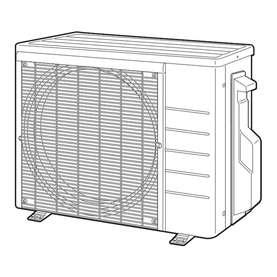
- Page 8 Outdoor Unit Installation Installing the outdoor unit • When installing the outdoor unit, refer to “Precautions for Selecting a Location” on page 3 and “Outdoor Unit Installation Diagram” on page 4. • If drain work is necessary, follow the procedures below. Drain work CAUTION In cold areas, do not use a drain socket, drain caps (1, 2) and a drain hose with the outdoor unit.
- Page 9 Refrigerant piping CAUTION • Use the flare nut fixed to the main unit. (This is to prevent the flare nut from cracking as a result of deterioration over time.) • To prevent gas leakage, apply refrigeration oil only to the inner surface of the flare. (Use refrigeration oil for R32 or R410A.) •...
- Page 10 Outdoor Unit Installation Pressure test and evacuating system WARNING • Make sure that air or any matter other than refrigerant (R32) does not get into the refrigeration cycle. • If refrigerant gas leaks should occur, ventilate the room as soon and as much as possible. •...
- Page 11 Wiring WARNING • RISK OF ELECTRIC SHOCK CAUSE INJURY OR DEATH. System contains oversize protective earthing (grounding) terminal which shall be properly connected. • Do not ground units to water pipes, gas pipes, telephone wires, or lightning rods as incomplete grounding can cause a severe shock hazard resulting in severe injury or death.
- Page 12 Wiring [Method of Mounting Conduit] • When wiring, remove the top plate and look at the wiring diagram on the back of the top plate. • A protection plate is fixed for protection from the high-voltage section. Wiring diagram Top plate 1) Dismount the stop valve cover by removing the screw.
- Page 13 Facility Setting (cooling at low outdoor temperature) WARNING Make sure to turn the power OFF before performing work. CAUTION • If the outdoor unit is installed where the heat exchanger of the unit is exposed to direct wind, provide a windbreak wall. •...
- Page 14 Pump Down Operation In order to protect the environment, be sure to pump down when relocating or disposing of the unit. 1) Remove the valve caps from the liquid stop valve and gas stop valve. Hexagonal 2) Begin forced cooling operation. wrench 3) After 5 to 10 minutes, close the liquid stop valve with a hexagonal wrench.
- Page 15 MEMO ■ English...
- Page 16 Two-dimensional bar code is a manufacturing code. 3P740832-1E M23B157C (2407) HT...
Need help?
Do you have a question about the RXT09AVJU9 and is the answer not in the manual?
Questions and answers