
Subscribe to Our Youtube Channel
Related Manuals for toscano Vigilec Compact V1B


Summary of Contents for toscano Vigilec Compact V1B
- Page 1 COMPACT Ed. 1.23 ENGLISH (EN) User manual Multi-control and multi-protection panel for 1 sewage pump...
- Page 2 ENGLISH (EN) 1. GENERAL DESCRIPTION ..................2 1.1. PRODUCT DESCRIPTION ....................2 1.3. FRONT CONFIGURATION ...................3 1.4. INTERIOR CONFIGURATION ..................4 2. INSTALLATION ....................5 2.1. MECHANICAL INSTALLATION (WALL FIXING) ............5 2.2. ELECTRICAL INSTALLATION | SINGLE PHASE SYSTEM .........6 2.3. ELECTRICAL INSTALLATION | THREE PHASE SYSTEM ..........8 3.
- Page 3 WARNING: If the equipment is used or modified outside of what is specified by the manufacturer, Toscano disclaims all responsibility for improper use. The interior of the equipment should only be handled by our technical service personnel. Installation must be performed by an electrician.
- Page 4 1. GENERAL DESCRIPTION 1.1. PRODUCT DESCRIPTION Control and Protection Panel for Sewage Pumps: controls and protects 1 pump via 2/3 level floats or 4-20 mA sensor. Key features include overload protection, pump alternation, and alarm outputs. It offers simple and intuitive handling for efficient operation. It guarantees precise control of the liquid level and prevents damage to the system.
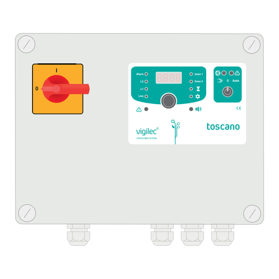
- Page 5 1.3. FRONT CONFIGURATION Front control panel Pump selector Parts of the Control Module 1. Alarm level (ALARM) 7. Advanced settings / Datalogger 2. Medium level (L1) 8. Alarm indicator 3. Low level (LOW) 9. Rotary push button 4. General alarm 10.
- Page 6 1.4. INTERIOR CONFIGURATION Current transformer Power transformer Contactor 0,2 A ON OFF Control terminal block 10 11 12 13 14 15 16 17 18 19 20 18 19 24VAC KLIXON ALARM VOLTAGE Klixon Input GENERAL 230V ALARM 4-20 400V Grounding strip Control fuses Voltage selection Main switch...
- Page 7 2. INSTALLATION 2.1. MECHANICAL INSTALLATION (WALL FIXING) ● Clamping brackets mounting Place the fixing brackets in one of the anchor points established for this purpose. Drill holes in the wall using the location where you have placed the fixing brackets. Place the screws to anchor the equipment using the fixing claws.
- Page 8 2.2. ELECTRICAL INSTALLATION | SINGLE PHASE SYSTEM The correct electrical installation of a single phase pump system is crucial to guarantee effi cient and safe operation of this panel. Follow the steps below carefully: Position the selectors on - 0 -. Move the voltage selection jumper to the 230 V position.
- Page 9 Single phase power input Single phase pump output with (L/N, 230 VAC) integrated starting capacitor Single phase pump output with separate starting capacitor L N C...
- Page 10 2.3. ELECTRICAL INSTALLATION | THREE PHASE SYSTEM The correct electrical installation of a three phase pump system is crucial to guarantee effi cient and safe operation of this panel. Follow the steps below carefully: Position the selectors on - 0 -. Move the voltage selection jumper to the 230 V or 400 V position, depending on the type of motor you have chosen.
- Page 11 Three phase power input Output to three phase pump. (L1/L2/L3, 230/400 VAC). W X X (phase sequence error) appears when turning on, two of the E rr PHA5 power supply phases must be swapped with each other. ● Verifi cation of the direction of rotation Hang up the pump and turn on for a moment using the ´´manual´´...
- Page 12 3. HANDLING OF EQUIPMENT 3.1. PUMP SELECTOR Manual mode Zero mode Automatic mode The pump works in The pump The pump will start forced operation for a can’t work when necessary maximum of 15 seconds If none of the selectors are in AUTO, the equipment activates the alarm 3.2.
- Page 13 3.3. DISPLAY MESSAGES The selector is at zero (system disabled). Equipment in Automatic mode. aut0 Pump operating (consumption of 3.4 Amps). 3. 4 A Neither of the selectors are in AUTO. Stopping of the pumps in the course of timing (pg.14). t -25 Failure or incorrect sequence in power supply phases (pg.
- Page 14 4. SETTINGS / CONFIGURATION 4.1. THERMAL PROTECTION SETTINGS ● Manual setting Imax Select Press Modify value Release when Hold down value appears If you do not touch the control for more than 15 seconds, the device will return to the main screen. ●...
- Page 15 ● Phase failure If, in a three phase installation, the direction changes or one of the phases in the power supply or in the pump is cut, an phase failure will occur. Err PHA5 ERROR ERROR ● Motor overheating (KLIXON) If the pump has an integrated thermocontact (KLIXON or similar), we can connect them to terminals 1-2 and 3-4.
- Page 16 4.2. MECHANICAL PROTECTION SETTINGS ● Maximum running time Allows detection of the blockage of the lower fl oats or of the sensor by analysing the time that it pumps with only the lowest level activated. Select Max. Hold down Select the Press and hold run time desired time...
- Page 17 Detection of blockages in continuous level sensor If the sensor gets stuck and the tank empties the tank empties the reading does not drop below the LOW level and the pumps do not stop. When any pump is in operation with only LOW activated, the LED flashes. If the maximum time is exceeded, the LOW level is cancelled and the LED lights up.
- Page 18 4.3. LEVEL CONTROL SETTINGS / PUMP WITH INTEGRATED FLOAT OPERATION The equipment keeps one of the outputs activated. When the tank fi lls up, the pump fl oats go up at the same time, but only one of the pumps will start. Alarm fl oat Integrated fl oats - Activates the buzzer.
- Page 19 SETTINGS Set the selector to zero before confi guring the equipment. We will choose one of the following options: Alarm Option A. Without additional fl oat - We put a jumper in 16-17 terminal. 14 15 16 17 18 19 20 21 Alarm Option C.
- Page 20 4.4. LEVEL CONTROL SETTINGS / PUMP WITH 2 EXTERNAL FLOATS OPERATION 14 15 16 17 18 19 Alarm fl oat ALARM - Activates the buzzer. - Activates the GENERAL ALARM output. - Activates the 24 VAC output. Alarm Alarm Level L1 - Starts the pump.
- Page 21 4.5. LEVEL CONTROL SETTINGS / PUMP WITH 3 EXTERNAL FLOATS OPERATION 14 15 16 17 18 19 Alarm fl oat ALARM - Activates the buzzer. - Activates the GENERAL ALARM output. - Activates the 24 VAC output. Level L1 - Starts the pump. Alarm Alarm LOW level...
- Page 22 4.6. LEVEL CONTROL SETTINGS / PUMP WITH SENSOR DE NIVEL 4-20 mA OPERATION Control of the pumps by means of a 4-20 mA sensor + alarm fl oat allows us to adjust up to 3 levels. The sensor monitors the liquid level and activates the pump based on these preset levels.
- Page 23 SETTINGS Alarm Connections - Connect the sensor in terminal 12 and 13. 12 13 14 15 16 17 18 19 - The sensor mesh is connected 4-20 to the PE grounding strip. The use of an alarm float is recommended Range selection Level settings The equipment comes by default with the...
- Page 24 4.7. ADVANCED SETTINGS Rotate and select the Select settings (SET) Press desired parameter 4-20 mA Auto-reset by sensor External Antilock deactivated deactivated fl oat deactivated alarm level 8sec 8sec 8sec 8sec 8sec 8sec Integrated Antilock Auto-reset Shows Factory fl oat activated by activated saved data...
- Page 25 ● External fl oat/integrated fl oat The advanced configuration mode allows you to select between the option of integrated floats or external floats in the installation. Depending on the choice, the corresponding mode must be set to ensure proper operation. See section 4.3. LEVEL CONTROL SETTINGS.
- Page 26 5. ALARMS / SIGNALLING OUTPUTS 5.1. SIGNALLING OUTPUT (TERMINALS 5-6/7-8) ● Beacon light option with 24 VAC power supply (max. 500 mA) ● Activates if any problem is detected (see page 26). ● Allows the direct connection of a signalling device to 24 VAC, such as a beacon or an additional buzzer.
- Page 27 5.2. GENERAL ALARM OUTPUT (TERMINALS 9-10-11) ● If everything is correct, the contact is located between terminals 9 and 10. When there is a problem, the contact is between 10 and 11. ALARM 2 A / 250 V GENERAL ALARM Potential free output (NO/ NC changeover contact) 5.3.
- Page 28 5.4. ALARM MESSAGES / TROUBLESHOOTING Possible Possible Message Description cause solution Power the equipment Mains supply OFF respecting the input voltage (see page 6-9) The screen Move the main switch The main switch is in - 0 - does not turn to - 1 - Make sure that the flat ribbon is correctly...
- Page 29 4-20 mA The sensor is not Check the sensor sensor error connected. connection (terminals 12- Err. 5EN due to open It’s consuming less than 13) to see that it is wired 0. C circuit correctly The sensor is short- Change the sensor circuited 4-20 mA Err.
- Page 30 6. FACTORY RESET Select SET Press Rotate and select F.rES Hold down Release when F.rES appears The counters for hours, start ups, alarms and last alarm will not be deleted. ● Default parameters Et.FL : Choice of the type of pump used: Pumps with external floats. Ablo OFF: Function disabled (OFF) for the automatic exercise of the pump 1 second every 50 hours of continuous stop.
- Page 31 7. MAINTENANCE 7.1. CONSULTATION OF OPERATING DATA (DATALOGGER) Select SET Press Press and release Pump 1 Nº of Nº of Current of the Version Operating startups alarms last alarm trip hours software You can stop this message with a short press of the control.
- Page 32 7.2. MAINTENANCE ADVICE ● Regular inspection Carry out regular inspections of the entire control and protection panel system for sewage pumps. Check components, cables, connections, and protection devices for signs of wear, damage, or deterioration. Check and tighten electrical connections and terminals to ensure they are tight and free of signs of corrosion.
- Page 33 8. TECHNICAL CHARACTERISTICS Electrical characteristics Supply voltage 230/400 VAC (selectable) Permissible voltage variations +/-20% (>30%: Self-disconnection) Control fuses (F1/F2) F1: 0.3 A (primary) / F2: 2A (secondary) Maximum current 16A AC3 Protections Overload, failure or incorrect phase sequence, overheating and maximum running time Display LED 4 digits Signalling...
- Page 34 NOTES...
- Page 36 Toscano Línea Electrónica, S.L. Av. A-92, Km. 6,5 - 41500 - Alcalá de Guadaíra - SEVILLE - SPAIN (+34) 954 999 900 - www.toscano.es - info@toscano.es...
Need help?
Do you have a question about the Vigilec Compact V1B and is the answer not in the manual?
Questions and answers