Advertisement
Available languages
Available languages
Quick Links
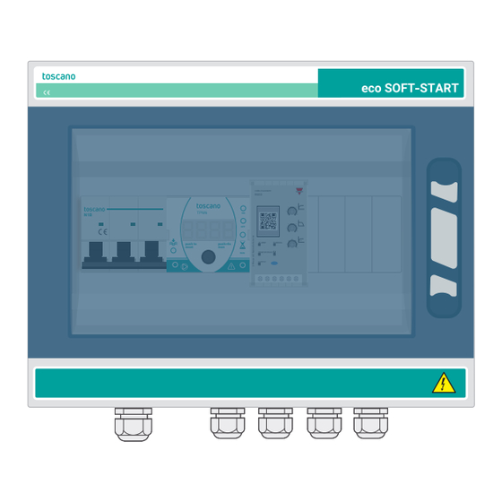
ECO-SOFTSTART
400V
0V
230V
PUMP
LEVEL
ALARM
CARLO GAVAZZI
RSGD
N1B
ON
OFF
push to
push>4s
ALARM
reset
man
RUN
RAMP/BY/PASS
SUPPLY
EXT.ON/OFF
C.TR
ECO
ESPAÑOL ( ES ) Manual de usuario
Cuadro digital de control y protección de 1 bomba hasta
16A, 230 o 400 VAC, 3ph, multicontrol, con arranque
progresivo.
t
7
5
10
2
15
1
20
t
5
7
10
2
15
1
20
t
10
8
12
FLC
MANUAL
7
14
ENGLISH ( EN ) User manual
6
16
Simplex control and protection panel up to 16A, 230 or
400 VAC, multicontrol, with sofstart.
FRANÇAIS ( FR ) Guide d'utilisation
Coffret digital de commande et protection pour 1 pompe
jusqu'à 16 A, 230 ou 400 VAC, multi-contrôle, avec
démarrage progresif
DEUTSCH ( DE ) Bedienungsanleitung
Simplex Steuer- und Schutzbedienfeld bis zu 16A, 230
oder 400 VAC, Multicontrol
Ed. 1.21
Advertisement

Subscribe to Our Youtube Channel
Related Manuals for toscano Vigilec ECO-SOFTSTART


Summary of Contents for toscano Vigilec ECO-SOFTSTART
- Page 1 ECO-SOFTSTART Ed. 1.21 ESPAÑOL ( ES ) Manual de usuario Cuadro digital de control y protección de 1 bomba hasta 16A, 230 o 400 VAC, 3ph, multicontrol, con arranque progresivo. 400V 230V PUMP LEVEL ALARM CARLO GAVAZZI RSGD push to push>4s ALARM MANUAL...
- Page 2 CONTENIDO / CONTENT ESPAÑOL (ES) 1. MÓDULO DE CONTROL ..................2 2. ARRANCADOR ESTÁTICO .................. 3 3. MONTAJE ......................4 4. CONEXIONADO DE FUERZA................5 5. CONEXIONADO DE CONTROL ................6 6. CONTROL EXTERNO ................... 9 7. SALIDA DE ALARMA..................10 8.
- Page 3 SOMMAIRE / INHALTSVERZEICHNIS FRANÇAIS (FR) 1. MODULE DE CONTRÔLE ET PROTECTION ............26 2. CONSULTATION DES PARAMÈTRES ENREGISTRÉS ........27 3. FIXATION DU COFFRET ..................28 4. RACCORDEMENTS ÉLECTRIQUES ..............29 5. COMMANDE EXTERNE ..................32 6. PROTECTION THERMIQUE DU MOTEUR ............33 7.
- Page 4 ADVERTENCIA: Si el equipo se usa o modifica fuera de lo especificado por el fabricante, Toscano se exime de toda responsabilidad por uso inadecuado. El interior del equipo sólo debe ser manipulado por personal de nuestro servicio técnico.
- Page 5 AVERTISSEMENT: Une protection supplémentaire du moteur de la pompe peut être ajoutée si nécessaire dans l’installation. AVERTISSEMENT: Si l’équipement est utilisé ou modifié en dehors des spécifications du fabricant, Toscano décline toute responsabilité en cas d’utilisation non conforme. L’intérieur de l’équipement ne doit être manipulé que par le personnel de notre service technique. WARNUNG ACHTUNG! Vor jeder Einstellung ist es erforderlich, den Motor an das Gerät anzuschließen, um unerwartete...
- Page 6 1. MÓDULO DE CONTROL Pilotos 1. Nivel bajo 2. Bomba en marcha 400V 230V PUMP LEVEL ALARM 3. Ajuste de sobrecarga 4. Ajuste de bajacarga 5. Ajuste de tiempo de rearme 6. Alarma Imax Imin Entradas/Salidas push>4s push to reset A.
- Page 7 2. ARRANCADOR ESTÁTICO CARLO GAVAZZI RSGD ALARM MANUAL RAMP/BY/PASS SUPPLY Potenciómetros de ajustes ● I. Ajuste de tiempo de rampa de arranque Puede ajustarse entre 5 y 20 segundos ● II. Ajuste de tiempo de rampa de parada Puede ajustarse entre 5 y 20 segundos ●...
- Page 8 3. MONTAJE Fijación directa Para anclar el equipo a la pared, en primer lugar se debe retirar la tapa frontal del equipo. Tras esto, habrá que perforar en los lugares indicado para ello y fijar el equipo a la pared mediante tornillos.
- Page 9 4. CONEXIONADO DE FUERZA 400V 230V PUMP LEVEL ALARM CARLO GAVAZZI RSGD ALARM MANUAL push>4s push to reset RAMP/BY/PASS SUPPLY EXT.ON/OFF C.TR 400VAC ( L1-L2-L3 ) 400VAC ( L1-L2-L3 )
- Page 10 5. CONEXIONADO DE CONTROL push>4s push to ● reset Bornas de control EXT. ON/OFF: 9 y 10 Nivel bajo: 11 Nivel alto: 12 Tierra: 13 EXT.ON/OFF EXT.ON/OFF C.TR ● ● 9 10 11 12 13 No usado Sonda adicional para depósito aislante Si no se usa habrá...
- Page 11 1 Sondas + Tiempo de rearme ● 1 sonda + tiempo de rearme 9 10 11 12 13 Para usarlo es necesario puentear la entrada de sonda de nivel alto (11) con la entrada de sonda de nivel bajo (12) y seleccionar un tiempo de rearme entre 3 min.
- Page 12 ● Una boya 9 10 11 12 13 Cuando el nivel hace subir la boya, la bomba arranca. La bomba sigue en marcha hasta que la boya baja. ● Dos boyas 9 10 11 12 13 Cuando el nivel hace subir la boya de nivel alto, la bomba arranca.
- Page 13 6. CONTROL EXTERNO ● No usado 9 10 11 12 13 Si no se quiere usar la entrada basta simplemente con hacer un puente entre la borna 9 y 10. ● Boya 9 10 11 12 13 Se puede conectar una boya que detecte que el nivel está...
- Page 14 7. SALIDA DE ALARMA El módulo de control TPM6 incorpora una salida de alarma, a la cual se puede conectar cualquier dispositivo de señalización que funcione a 230 VAC o 400VAC y con un consumo máximo de 1A. Esta salida se activa en caso de: •...
- Page 15 8. MANEJO Pasar de -0- a Auto Estamos en -0- Pulsamos Pasamos a Auto Imax Imax Imax Imin Imin Imin push>4s push to push to push>4s push to push>4s reset reset reset Pasar de Auto a -0- Pasamos a -0- Estamos en Auto Pulsamos Imax...
- Page 16 9. AJUSTE IMAX, IMIN Y TIEMPO DE REARME Ajuste automático El equipo se autoajusta con la 1º puesta en marcha. Tras los primeros 60 segundos, el equipo registra las corrientes máxima y mínima consumidas por la bomba. Después fija el valor de Imax. un 10% por encima de la máxima corriente registrada y el valor Imin.
- Page 17 Tiempo de rearme Es el tiempo que temporiza la bomba antes de arrancar de nuevo. Se utiliza en los modos “1 sonda” y “sin sondas”. Para el modo “2 sondas”, es necesario seleccionar el valor “OFF”. Ajuste manual de Imax, Imin o tiempo de rearme El equipo se autoajusta con la primera puesta en marcha.
- Page 18 10. MENSAJES DE ALARMA Imax Imax Imin Imin push>4s push>4s push to push to push to reset reset reset Sobrecarga Bajacarga Imax Imax Imax Imin Imin Imin Imin Imin push>4s push>4s push to push to reset reset Frecuencia excesiva de arranques Falta de fase (>30 arranques/hora) Reset de alarmas...
- Page 19 11. DATALOGGER Seleccionar Pulsar Pulsar de nuevo Imax Imax Imax Imin Imin Imin push to push>4s push to push>4s push to push>4s reset reset reset Imax Imin Imin push>4s push to reset 1 - Horas de marcha 2 - Arranques 3 - Alarmas 4 - Intensidad última alarma 5 - Versión del software...
- Page 20 12. ESPECIFICACIONES TÉCNICAS Tensión de alimentación Trifásica a 400Vac Variación de tensión admisible +/-20% (>30%: Autodesconexión ) Protecciones Sobrecarga, bajacarga, fallo y secuencia de fases, frecuencia de arranque excesiva Información en display Consumo de la bomba, intensidad de fallo, tiempo de rearme restante y modo de funcionamiento Intensidad máxima de la bomba 16A hasta 40ºC, 15A hasta 50ºC y 13A hasta 60ºC Intensidad mínima de la bomba...
- Page 21 NOTAS...
- Page 22 1. CONTROL MODULE LED lights 1. Low Level 2. Pump running 400V 230V PUMP LEVEL ALARM 3. Overload setting 4. Underload setting 5. Restart time setting 6. Alarm Imax Imin Inputs/Outputs push>4s push to reset A. Power supply input B. Pump control output C.
- Page 23 2. SOFT STARTER CARLO GAVAZZI RSGD ALARM MANUAL RAMP/BY/PASS SUPPLY Adjustment potentiometers ● I. Start ramp time setting Can be set between 5 and 20 seconds ● II. Stop ramp time setting Can be set between 5 and 20 seconds ●...
- Page 24 3. MOUNTING (WALL FIXING) Direct wall mounting To fix the panel to the wall, the front cover must be removed. Then, drill holes in the indicated places and fix the unit to the wall with screws. 400V 230V PUMP LEVEL ALARM 400V CARLO GAVAZZI...
- Page 25 4. POWER CONNECTION 400V 230V PUMP LEVEL ALARM CARLO GAVAZZI RSGD ALARM MANUAL push>4s push to reset RAMP/BY/PASS SUPPLY EXT.ON/OFF C.TR 400VAC ( L1-L2-L3 ) 400VAC ( L1-L2-L3 )
- Page 26 5. LEVEL CONTROL INPUTS push>4s push to ● reset Control terminals EXT. ON/OFF: 9 & 10 Low level: 11 High level: 12 GE: 13 EXT.ON/OFF EXT.ON/OFF C.TR ● ● 9 10 11 12 13 Not used Additional level probe for isolated tank When the level control is not...
- Page 27 1 Sondas + Tiempo de rearme ● 1 probe + reset time 9 10 11 12 13 To use this mode, it is necessary to bypass the high level probe input (11) with ground (12) and select a reset time between 3 min. and 99 h.
- Page 28 ● 1 float switch 9 10 11 12 13 When the level raises the float, the pump starts. The pump continues to run until the float drops. ● 2 float switches 9 10 11 12 13 When the level raises the high level float, the pump starts.
- Page 29 6. EXTERNAL CONTROL ● Not used 9 10 11 12 13 If you do not want to use the input, , it is necessary to bypass terminals 9 and 10. ● Float 9 10 11 12 13 A float can be connected to detect that the level is above or below and automatically open the contact to stop the pump.
- Page 30 7. ALARM OUTPUT TPM6 control module incorporates an alarm output, to which any signalling device operating at 230 VAC or 400VAC and with a maximum power consumption of 1A can be connected. It is activated in case of : • Overload alarm, •...
- Page 31 8. OPERATION How to switch from -0- to Auto Display -0- Press Now you are in Auto Imax Imax Imax Imin Imin Imin push>4s push to push to push>4s push to push>4s reset reset reset How to switch from Auto to -0- Now you are in OFF Display Auto Press...
- Page 32 9. IMAX, IMIN AND RESTART TIME Automatic adjustment The equipment adjusts itself with the 1st start-up. After the first 60 seconds, the equipment registers the maximum and minimum current consumption of the pump. Then, the controller sets the maximum current value a 10% above the maximum recorded current and the minimum current value a 10% below the minimum recorded current.
- Page 33 Restart time This is the time the pump is timed before restarting. It is used in the “1 probe” and “without probes” modes. For the “2 sensors” mode, the value “OFF” must be selected. Manual setting of Imax, Imin or restart time The device is self-calibrating at the first start-up.
- Page 34 10. ALARM MESSAGE Imax Imax Imin Imin push>4s push>4s push to push to push to reset reset reset Overload Underload Imax Imax Imax Imin Imin Imin Imin Imin push>4s push>4s push to push to reset reset Excessive frequency of starts Phase loss (>30 starts/hour) Alarm reset...
- Page 35 11. DATALOGGER Select Press the knob Press the knob again Imax Imax Imax Imin Imin Imin push to push>4s push to push>4s push to push>4s reset reset reset Imax Imin Imin push>4s push to reset 1 - Total pump working hours 2 - Total pump starts counter 3 - Alarms 4 - Last alarm current tripping value...
- Page 36 12. TECHNICAL CHARACTERISTICS Power supply 400VAC 3-ph Admissible voltage variation +/-20% (>30%: Auto Power Off) Protections Overload, Underload, Phase loss, Excessive starting frequency Display information Pump consumption, fault current, remaining restart time and operating mode Maximum pump current 16A up to 40ºC, 15A up to 50ºC and 13A up to 60ºC Minimum pump current 1 A (For correct operation of the soft starter) Maximum pump power...
- Page 38 Toscano Línea Electrónica, S.L. Av. A-92, Km. 6,5 - 41500 - Alcalá de Guadaíra - SEVILLA - SPAIN (+34) 954 999 900 - www.toscano.es - info@toscano.es...
Need help?
Do you have a question about the Vigilec ECO-SOFTSTART and is the answer not in the manual?
Questions and answers