Table of Contents
Advertisement
Quick Links
Advertisement
Table of Contents

Related Manuals for toscano vigilec VHP-DRAIN-2


Summary of Contents for toscano vigilec VHP-DRAIN-2
- Page 1 CABINET VHP-DRAIN-2 Ed. 3.22 ENGLISH ( EN ) User manual Duplex control and protection panel for 2 drain pumps, 1ph/3ph 230/400VAC with DOL or SFS starting method ALARM TPM DRAIN 2 MODE HIGH P1-OFF push>4s push to reset P2-OFF ALARM MUTE VHP-DRAIN-2-DOL VHP-DRAIN-2-SFS...
-
Page 2: Table Of Contents
CONTENT ENGLISH (EN) 1. MODELS ....................... 2 2. FRONT DISPLAY ....................3 3. INTERNAL LAYOUT..................... 4 4. SETTING-UP (WALL MOUNTING) ..............5 5. VOLTAGE SELECTION ..................6 6. POWER CONNECTIONS ..................7 7. MOTOR CONNECTIONS ..................8 8. LEVEL CONTROL INPUTS .................. 9 9. -
Page 3: English (En)
WARNING: Additional protection of the pump motor may be added when necessary in the installation. WARNING: If the equipment is used or modified outside the manufacturer’s specifications, Toscano disclaims all liability due to improper use. The interior of the equipment should only be handled by personnel of our technical service. -
Page 4: Models
1. MODELS ALARM MODE TPM DRAIN 2 HIGH P1-OFF push to push>4s reset 10003738 VHP-DRAIN-2-DOL-1,6/2,5A P2-OFF ALARM TPM DRAIN 2 MODE HIGH P1-OFF push>4s push to reset P2-OFF 10003739 VHP-DRAIN-2-DOL-2,5/4A 10003740 VHP-DRAIN-2-DOL-4/6,3A 10003741 VHP-DRAIN-2-DOL-6,3/10A ALARM MUTE ALARM MUTE 10003742 VHP-DRAIN-2-DOL-10/16A 10003743 VHP-DRAIN-2-DOL-14,5/20A 10003744... -
Page 5: Front Display
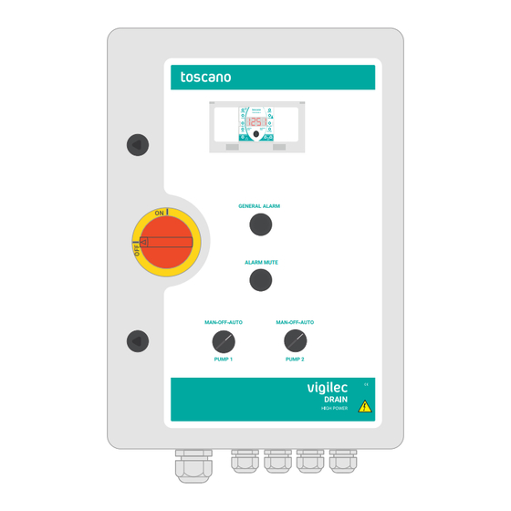
2. FRONT DISPLAY Key locking Control module ALARM MODE TPM DRAIN 2 HIGH P1-OFF push>4s (TPM-DRAIN-2) push to reset P2-OFF Audible alarm for: • High level • Supply failure • Motor(s) failure • 4-20mA sensor Main switch failure (ON-OFF) ALARM MUTE Silencer for audible alarm MAN-OFF-AUTO... -
Page 6: Internal Layout
3. INTERNAL LAYOUT VHP-DRAIN-2-DOL Motor protector circuit breaker Free space for DIN-rail (per pump) accesories (GSM, hourmeters, heater, etc) Control circuit breakers Voltage selecion. Dual voltage Main switch with 230V I/III or 400V III external lockable protection Isolated control Power contactor transformer 24V (per pump) (EN 61558) -
Page 7: Setting-Up (Wall Mounting)
4. SETTING-UP (WALL MOUNTING) Clamping brackets mounting Place the fixing brackets in the anchor points established for this purpose. Drill holes in the wall using the location where you have placed the fixing brackets. Insert the screws to anchor the equipment by using the fixing brackets. -
Page 8: Voltage Selection
5. VOLTAGE SELECTION Only for DOL model. 230 VAC 400 VAC The cabinets are set at 400V by default. Power supply VHP-DRAIN-2-DOL at 230VAC: In case of single-phase power supply, wire the motor protectors as indicated below. The equipment includes 2 cables supplied for this purpose. -
Page 9: Power Connections
6. POWER CONNECTIONS L1 L2 L3 PE KLIXON KLIXON 1-phase 230 VAC 3-phase L1 L2 L3 PE 400 VAC Only for SFS model. 9 10 PE • Connect the 3 input phases L1/L2/L3 in the correct order, otherwise HIGH ALARM the softstarter will fail. -
Page 10: Motor Connections
7. MOTOR CONNECTIONS L1 L2 L3 PE KLIXON KLIXON L1 L2 L3 PE 8 9 10 PE HIGH ALARM LEVEL LEVEL LEVEL LEVEL SENSOR 3-phase 400 VAC KLIXON KLIXON 1-phase 230 VAC PUMP 1 PUMP 2 • Connect the 3 motor output phases U/V/W and check that the motor turns in the correct direction. -
Page 11: Level Control Inputs
8. LEVEL CONTROL INPUTS KLIXON KLIXON 8 9 10 PE HIGH ALARM LEVEL LEVEL LEVEL LEVEL SENSOR 8 9 10 PE HIGH ALARM LEVEL LEVEL LEVEL LEVEL SENSOR P1 = Pump 1 P2 = Pump 2 8 9 10 HIGH ALARM HIGH ALARM... -
Page 12: Alarm Output
9. ALARM OUTPUT GENERAL PUMP 1 PUMP 2 ALARM ALARM ALARM OUTPUT OUTPUT OUTPUT DRY CONTACT ALARM OUTPUT 1A/250VAC MAX EACH WET CONTACT 24VAC/5A MAX The general alarm outputs will close and activate the general alarm in the event of: •... - Page 13 GENERAL PUMP 1 PUMP 2 ALARM ALARM ALARM OUTPUT OUTPUT OUTPUT DRY CONTACT ALARM OUTPUT 1A/250VAC MAX EACH WET CONTACT 24VAC/5A MAX Voltage-free alarm contacts, 1A Alarm contact 24VAC / 5A MAX / 250 VAC MAX. • External signalling of the equipment •...
-
Page 14: Disabling Audible Alarm
10. DISABLING AUDIBLE ALARM 230 VAC The equipment is supplied with an acoustic alarm buzzer to signal the faults or warnings indicated above. In the event of not requiring the acoustic alarm provided, disconnect the cable marked on terminals 1 and 2 shown in the image. -
Page 15: Control Module Signalling
11. CONTROL MODULE SIGNALLING Control module layout +24 4-20mA ALARM HIGH ALARM MODE TPM DRAIN 2 HIGH P1-OFF push>4s push to reset P2-OFF ALARM P1 ALARM BUZZER BAT 9V 1. Alarm level Alarm fl oat status indication. 2. Current water level (high) Status indication of HIGH fl oat (high level). - Page 16 ALARM MODE ALARM MODE ALARM MODE ALARM HIGH HIGH Control module LED signalling HIGH HIGH P1-OFF P1-O ● ● During adjustment In operation ALARM MODE P1-OFF ALARM P1-OFF P2-OFF P2-O Parameter selection “Operating mode setting and Pump 1 running HIGH MODE HIGH P2-OFF...
-
Page 17: Control Module Connections
12. CONTROL MODULE CONNECTIONS 24VAC 1 1 1 2 2 2 2 3 3 3 3 4 4 4 4 5 5 5 5 6 6 6 6 7 7 7 7 8 8 8 9 9 9 +24 4-20mA ALARM HIGH ALARM... -
Page 18: Manual Operation Mode And Pump Off
13. MANUAL OPERATION MODE AND PUMP OFF To activate the manual mode, keep the selector switch in the -MAN- position for each pump. In this case, the protections will remain disabled. This mode is used for test runs or to check the direction of rotation of the pump. MODE TPM DRAIN 2 Manual mode... -
Page 19: Locking And Unlocking [Prot - Free]
14. LOCKING AND UNLOCKING [PROT - FREE] TPM-DRAIN-2 prevents unwanted confi guration changes. [Prot] is displayed on the screen for 2 seconds. The unit always starts up in protected/locked mode. If there is no action after 5 minutes, the control module will automatically lock. Unlock ALARM ALARM... -
Page 20: Operating Modes
15. OPERATING MODES ● Selection of the fl oat switch operating mode. 2 fl oats mode 3 fl oats mode 3 fl oats mode 4-20mA sensor mode 4-20mA sensor mode ALARM ALARM MODE ALARM MODE ALARM MODE ALARM MODE TPM DRAIN 2 TPM DRAIN 2 TPM DRAIN 2 TPM DRAIN 2... - Page 21 ● Selection of the 4-20mA sensor + alarm fl oat operating mode. 2 fl oats mode 2 fl oats mode 3 fl oats mode 3 fl oats mode 3 fl oats mode 3 fl oats mode 4-20mA sensor mode ALARM ALARM MODE ALARM...
-
Page 22: Low Level Float Switch Anti-Lock System
16. LOW LEVEL FLOAT SWITCH ANTI-LOCK SYSTEM The LOW fl oat is responsible of stopping the pumps when the level drops. If this fl oat is blocked or stops working, the pumps will be at risk of dry running. This function protects the pumps by means of a confi gurable maximum running time. -
Page 23: Additional Functions
17. ADDITIONAL FUNCTIONS Detection of fl oat blockage This function allows the pumps to keep running in the event that the MED, HIGH or ALARM fl oats become blocked or stop working. The equipment will continue to operate even if any of the fl oats are blocked. The light of the blocked fl oat will fl ash and will display the message: Example situation: ALARM... -
Page 24: Alarm Messages
18. ALARM MESSAGES Unit has detected a problem. Alarm reset/mute alarm A revision is required. ALARM MODE TPM DRAIN 2 HIGH Float blocked. P1-OFF push to push>4s reset P2-OFF Sensor obstructed or damaged. Press to delete Sensor short-circuit the message Sensor open circuit The acoustic alarm is triggered in the event of: ALARM... -
Page 25: Datalogger
19. DATALOGGER ALARM ALARM MODE ALARM MODE ALARM MODE ALARM MODE TPM DRAIN 2 TPM DRAIN 2 TPM DRAIN 2 TPM DRAIN 2 TPM DRAIN 2 HIGH HIGH HIGH HIGH HIGH P1-OFF P1-OFF P1-OFF P1-OFF push to push>4s push to push>4s push to push>4s... -
Page 26: Technical Characteristics
20. TECHNICAL CHARACTERISTICS Dual-voltage 230 VAC I/III and 400 VAC III - 50/60 Hz Power supply Level status, Pumps status, Float switch status, Control mode, Led signaling Max. running time, Alarm, Pumps out of service Overload and Overheating (Klixon). Phase-loss and Phase Pump protections sequence (optional) Displayed information... -
Page 27: Additional Devices
21. ADDITIONAL DEVICES Optional devices to complete the external alarm outputs monitoring. GSM-BOX / TGSM-2 FLASH-BEACON-BOX GSM communication box/module Alarm panel with LED fl ash light GSM-BOX TGSM2 Adj. 10.8~13.8 V TGSM2 TGSM2 Max. 1.25 A Max. 15Watt INPUT 100~400VAC 0.5 A 50/60Hz OUTPUT... - Page 28 User manual digital version Toscano Línea Electrónica, S.L. Av. A-92, Km. 6,5 - 41500 - Alcalá de Guadaíra - SEVILLA - SPAIN (+34) 954 999 900 - www.toscano.es - info@toscano.es...
Need help?
Do you have a question about the vigilec VHP-DRAIN-2 and is the answer not in the manual?
Questions and answers