Table of Contents
Advertisement
Quick Links
Advertisement
Table of Contents

Related Manuals for Krystufek PANCONTROL PAN 100AD+


Summary of Contents for Krystufek PANCONTROL PAN 100AD+
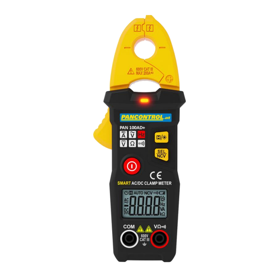
- Page 1 English PAN 100AD+...
-
Page 2: Table Of Contents
English Manual PAN 100AD+ Intelligent digital clamp meter Contents Introduction ..................3 Scope of delivery ................3 Safety Instructions................4 Symbols Description ................ 6 Panel Description ................7 Symbols of the Display ..............9 General Specifications ..............10 Operating Instructions ..............12 Maintenance ................. -
Page 3: Introduction
English 1. Introduction Thank you for purchasing PANCONTROL. Since 1986, the PANCONTROL brand has stood for practical, innovative and professional measuring instruments. We hope you enjoy using your new product and we are convinced that it will serve you well for many years to come. Please read this operating manual carefully before using the device to become familiar with the proper handling of the device and to prevent faulty operations. -
Page 4: Safety Instructions
English 3. Safety Instructions To ensure the safe use of the device, please follow all the safety and operating instructions given in this manual. • Before using the device, make sure that test leads and the device are in good condition and the device is working properly. (e.g. by connecting to known voltage sources). - Page 5 English • Do not use the device outdoors, in humid surroundings or in environments that are subjected to extreme temperature fluctuations. • Never use the device in an explosionprone environment. • Do not store the device in places which are exposed to direct sunlight. •...
-
Page 6: Symbols Description
English 4. Symbols Description Conforms to the relevant European Union directive (EN-61010) Product is protected by double insulation Risk of Danger. Important information See instruction manual Hazardous voltage! This product should not be disposed along with normal domestic waste at the end of its service life but should be handed over at a collection point for recycling electrical and electronic devices. -
Page 7: Panel Description
English 5. Panel Description... - Page 8 English Main switch Function keys (meaning see below.) Display Input terminal (Joint connector (COM) / Multi-function jack (V, , Induction clamp / Clamp opener NCV - Sensor / NCV - Display The function keys and their meanings (2.1) xHx Data hold (keep displayed value) / Backlight (2.2) SEL Function selector switch (-button) / Non Contact Voltage...
-
Page 9: Symbols Of The Display
English 6. Symbols of the Display Power indicator Data hold (keep displayed value) AUTO Automatic range selection Non Contact Voltage tester Audible continuity Battery low Display set to zero (Zero) AC voltage / current DC voltage / current Frequency measurement Voltage measurement Current masurement ... -
Page 10: General Specifications
English 7. General Specifications Display 3 3/4 Digits (to 5999) Overload indicator Polarity automatically (minus sign for negative polarity) Jaw opening 20 mm Measuring rate 3 / s Category CAT III, 600 V (Usage condition) max. voltage to earth 600 V AC / DC Maximum current 100 A (AC / DC) Frequency range... - Page 11 English Accuracy of the value Function Range Resolution displayed in % *) 0,001 A AC current (A~) 60 A 0,01 A ±(2,5% + 8 digits) 100 A 0,1 A 0,001 A DC current (A=) 60 A 0,01 A ±(3,0% + 8 digits) 100 A 0,1 A AC voltage (V~)
-
Page 12: Operating Instructions
English 8. Operating Instructions • Always switch OFF the device when it is not in use. • Be aware of the Safety Instructions! (Chapter 3) Data hold If the reading could not be read during measurement due to difficult operation the „HOLD“-button could be pressed to freeze the display reading. - Page 13 English Note: Due to the high sensitivity the reading sometimes shows random values if the test leads are not connected to any signal. The reading stabilizes when the test leads are connected to the circuit to be tested. Do not use the device near strong magnetic fields (for e.g. welding transformer), as this can distort the display.
- Page 14 English AC Current measurement Switch the unit on with the main switch (1). Press the lever to open the induction jaw. Place the wire in the center of the pliers opening as far as possible and close the measuring pliers again. Once the reading stabilizes, read the value.
- Page 15 English Resistance measurement / Audible continuity Attention! To avoid electric shocks, turn off the current of the device being tested and unload all capacitors before performing the following measurements. Switch the unit on with the main switch (1). Attach the pin-plug of the black test lead to the COM-jack and the pin-plug of the red test lead to the multi-function jack.
-
Page 16: Maintenance
English 9. Maintenance Only authorized service technicians may repair the instrument. If the instrument is malfunctioning, please test: - Battery condition and polarity - Condition of the fuse(s) if available - Condition of the test leads (check by continuity-test) Changing the battery(s) Replace the battery(s) when the battery symbol or BATT is displayed on the LCD. -
Page 17: Guarantee And Spare Parts
We strive to deliver the quality of the operating instructions that you rightly expect from us. If you would like to help us improve our translations, please make us aware of any errors. Feel free to write to us at: office@krystufek.at...
Need help?
Do you have a question about the PANCONTROL PAN 100AD+ and is the answer not in the manual?
Questions and answers