Advertisement
Available languages
Available languages
Quick Links
ATTACH YOUR RECEIPT HERE AND REGISTER YOUR FAN AT FANIMATION.COM
READ AND SAVE THESE INSTRUCTIONS
Date Code
For best and quickest service please provide date code. You can find the date code on the carton,
hand-held remote (inside of the battery compartment), receiver or top of fan housing.
Questions, problems, missing parts? Before returning to your retailer, call our customer
service department at 1-888-567-2055,8 a.m.-5 p.m., EST, Monday-Friday.
Purchase Date
™
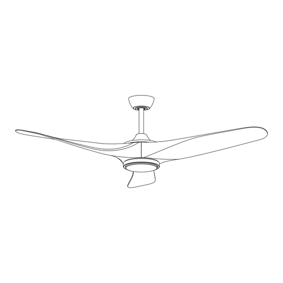
YARDLEY
CEILING FAN
Net Weight 20.29 lbs (9.2 kg)
MODEL #LP6821LBL
Español p. 23
Advertisement

Related Manuals for Fanimation YARDLEY LP6821LBL


Summary of Contents for Fanimation YARDLEY LP6821LBL
- Page 1 ™ YARDLEY CEILING FAN MODEL #LP6821LBL Español p. 23 ATTACH YOUR RECEIPT HERE AND REGISTER YOUR FAN AT FANIMATION.COM READ AND SAVE THESE INSTRUCTIONS Net Weight 20.29 lbs (9.2 kg) Date Code Purchase Date For best and quickest service please provide date code. You can find the date code on the carton, hand-held remote (inside of the battery compartment), receiver or top of fan housing.
- Page 2 Important Safety Instructions WARNING: To avoid fire, shock and serious personal injury, follow these instructions. 1. Read your owner’s manual and safety information before installing your new fan. Review the accompanying assembly diagrams. 2. Before servicing or cleaning unit, switch power off at service panel and lock service panel disconnecting means to prevent power from being switched on accidentally.
- Page 3 6. All costs of removal and reinstallation of the fan are the sole responsibility of the owner of the fan and not the store that sold the fan or Fanimation. 7. Fanimation reserves the right to modify or discontinue any product at any time and may substitute any part under this warranty.
- Page 4 Do not install or use fan if any part is damaged or missing. This product is designed to use only those parts supplied with this product and/or any accessories designated specifically for use with this product by Fanimation. Substitution of parts or accessories not designated for use with this product by Fanimation could result in personal injury or property damage.
- Page 5 8 - 9 feet from floor to the ceiling fan at low speed in the clockwise direction. blade for optimal airflow. Consult your Fanimation This produces a gentle updraft, which forces warm Retailer for optional mounting accessories.
- Page 6 Electrical and Structural Requirements (Continued) Brace use (Figure 3) Paired with a deep box, this hanger is meant to span CEILING JOIST between two joists and takes the place of wooden blocking. WARNING To reduce the risk of fire, electric shock, or personal injury, mount to outlet box marked acceptable for fan support of 15.9 kg (35 lbs) or less and use mounting screws provided with the outlet box.
- Page 7 How to Assemble Your Ceiling Fan Blades INSTALLATION NOTE 1/4″-20 Pan Head Screw With lock Washer/Flat Washer Do not connect fan blades until the fan is completely (3 each per blade) installed. Installing the fan with blades assembled may result in damage to the fan blades. Red Dot Red Dot WARNING...
- Page 8 How to Assemble Your Ceiling Fan 1. Remove the hanger ball portion from the downrod/ hanger ball assembly by loosening the set screw in the hanger ball until the ball falls freely down the downrod. Downrod Remove the pin from the downrod, then remove the hanger ball.
- Page 9 How to Assemble Your Ceiling Fan (continued) Thread downrod into the downrod support on top of the motor. Install the clevis pin by aligning the holes Downrod in the downrod support with holes in the downrod. Set Screws and Locking Nuts (2) Secure clevis pin with hairpin clip.
- Page 10 How to Hang Your Ceiling Fan WARNING To avoid possible fire or shock, be sure electricity is turned off at the main fuse box before hanging. (Figure 1) Main Fuse Box NOTE: If you are not sure if the outlet box is grounded, contact a licensed electrician for advice, as it must be grounded for safe operation.
- Page 11 How to Wire Your Ceiling Fan NOTE: If fan or supply wires are different colors than indicated, have this unit installed by a qualified electrician. Receiver 1. To set the code on receiver unit, slide dip switches to the same positions as set on the remote control. (Figure 1) Dip Switch NOTE: The remote unit has 32 different code combinations.
- Page 12 How to Wire Your Ceiling Fan (continued) 3. Connect wires using connectors as shown in Figure 4. WARNING Connect the 2 pin connectors from the motor assembly to the 2 pin connectors from receiver, connect the 3 pin Check to see that all connections are tight, connectors from the motor assembly to the 3 pin including ground, and that no bare wire is connectors from receiver.
- Page 13 NOTE: This step is applicable after the necessary wiring is completed. 1. Assemble canopy by rotating key slot in canopy over shoulder screw in hanger bracket and care not to pinch the wires. Tighten shoulder screw. Fully assemble and tighten second shoulder screw that was previously removed.
- Page 14 How to Assemble Your Light Kit CAUTION To reduce the risk of electric shock, disconnect the electrical supply circuit to the fan before installing your light kit. 1. Remove one of the three screws in the support bracket at the bottom of the motor assembly. Retain the screw for later and slightly loosen the remaining Motor two screws.
- Page 15 Assemble the LED assembly to the switch housing assembly using the two key slots. Replace the removed screw and secure all three screws. (Figure 5) CAUTION The light source is designed for this specific application and can overheat if serviced by untrained personnel.
- Page 16 How to Operate Your Ceiling Fan : Using a full range dimmer switch 1. IMPORTANT (not included) to control fan speed will damage the fan. To reduce the risk of fire or electrical shock, do not use a full range dimmer switch to control the fan speed.
- Page 17 How to Operate Your Ceiling Fan (continued) 5. To set the remote code same positions as the receiver with a small screwdriver or ball point pen (neither included), slide dip switches firmly up or down. (Figure 5) NOTE: Factory setting is all up. Do not use this position.
- Page 18 How to Install Your Remote Control Installing Wall Plate: (Figure 1) Attach wall plate using the two provided screws. Screws (2) Wall Plate Figure 1 Maintenance Periodic cleaning of your new ceiling fan is the only CAUTION maintenance that is needed. Do not use solvents when cleaning your ceiling fan.
- Page 19 1. The battery/batteries are going to 1. Please replace the battery/batteries. INDICATOR LED IS run out. CONSTANTLY FLASHING. 5. NOT ENOUGH AIR 1. If possible, consider using a longer MOVEMENT downrod (not included, you can buy the longer downrod from fanimation. com).
- Page 20 Before discarding packaging material, be certain all parts have been removed. HOW TO ORDER REPAIR PARTS When ordering repair parts, always give the following information: • Fan Model Number • Part Number • Part Description • Date Code Contact techsupport@fanimation.com or call 1.888.567.2055 for repair parts.
- Page 21 ™ Yardley Model LP6821LBL Exploded-View Illustration 13 (for use with optional longer downrods—sold separately) NOTE: The illustration shown is not to scale or its actual configuration may vary. Product/parts are subject to change without notice.
- Page 22 10983 Bennett Parkway Zionsville, IN 46077 Phone: 888-567-2055 Outside U.S.: 317-733-4113 FAX: 866-482-5215 2022/11 V.01 www.fanimation.com Copyright 2022 Fanimation...
- Page 23 ™ VENTILADOR DE TECHO YARDLEY MODELO #LP6821LBL ADJUNTE SU RECIBO AQUÍ Y REGISTRE SU VENTILADOR EN FANIMATION.COM LEA Y GUARDE ESTAS INSTRUCCIONES Código de fecha Fecha de compra Peso neto 9.2 kg (20.29 lbs) Para ofrecer un servicio rápido y de calidad, por favor suministre el código de fecha. Puede encontrar el código de fecha en el paquete, en el mando a distancia (dentro del compartimento de las pilas), en...
- Page 24 Instrucciones de seguridad importantes ADVERTENCIA: Siga estas instrucciones para prevenir incendios, descargas eléctricas y lesiones personales graves. Lea el manual del propietario y la información de seguridad antes de instalar su nuevo ventilador. Observe los diagramas de ensamblaje adjuntos. Antes de llevar a cabo el mantenimiento o la limpieza de la unidad, desconecte la electricidad en el panel de servicio y bloquee los medios de desconexión del mismo para evitar que se active accidentalmente.
- Page 25 1. GARANTÍA LIMITADA DE POR VIDA DEL MOTOR - Si se produjera una falla en alguna de las partes del motor de su ventilador debido a un defecto en los materiales o en la fabricación durante el tiempo de vida del comprador original, Fanimation proporcionará la pieza de repuesto sin cargo una vez que el ventilador defectuoso sea devuelto a nuestro centro de servicios nacional.
- Page 26 Fanimation específicamente para el mismo. La sustitución de piezas o accesorios que Fanimation no designó para usar con este producto podría ocasionar lesiones personales o daños en el ventilador. Póngase en contacto con su tienda si faltan piezas o hay piezas dañadas.
- Page 27 óptimo. Consulte en cerca del techo a bajar al espacio ocupado. No olvide su tienda minorista de Fanimation para obtener accesorios ajustar el termostato cuando utilice el ventilador de de montaje opcionales.
- Page 28 Requisitos eléctricos y estructurales (cont.) Uso del soporte (Figura 3) Conectado a una caja de distribución eléctrica, este Vigas del techo colgador sirve para abarcar el espacio entre dos vigas y ocupar el lugar de bloqueo de la madera. ADVERTENCIA Para reducir el riesgo de incendios, descargas eléctricas o lesiones personales, fije el ventilador a la caja de distribución eléctrica marcada como aceptable para soporte...
- Page 29 Cómo ensamblar su aspas del ventilador de techo 1/4″-20 tornillo de cabeza NOTA DE INSTALACIÓN plana con arandela plana/ No conecte las aspas hasta que el ventilador esté arandela de resorte totalmente instalado. Instalar el ventilador con las aspas (3 por conjunto por encima colocadas podría ocasionar daños en las mismas.
- Page 30 Cómo ensamblar el ventilador de techo 1. Extraiga la pieza de la bola colgante de la unidad de la bola colgante / varilla aflojando el tornillo de presión Pasador de la bola colgante hasta que la bola se libere de la Varilla varilla.
- Page 31 Cómo ensamblar el ventilador de techo (cont.) Coloque el soporte de la varilla y alinee los orificios de la clavija de horquilla en ambas piezas. Instale la Tornillo de Varilla clavija de horquilla y asegúrela con la pinza de fijación y las horquilla.
- Page 32 Cómo colgar el ventilador de techo ADVERTENCIA Para evitar una posible descarga eléctrica, asegúrese de cortar la alimentación eléctrica de la caja de PRINCIPAL CAJA DE FUSIBLES fusibles principal antes de colgar el ventilador. (Figura 1) NOTA: Si no está seguro de si la caja de salida tiene Figura 1 conexión a tierra, pida consejo a un electricista certificado, ya que debe tener conexión a tierra para...
- Page 33 Cómo realizar la instalación eléctrica del ventilador de techo NOTA: Si los cables de suministro o del ventilador son de colores diferentes que los indicados, contrate a un electricista calificado para que realice la instalación. Receptor 1. Para configurar el código de unidad del receptor. Interruptores Deslice los interruptores de código a las mismas posiciones que en el transmisor.
- Page 34 Cómo realizar la instalación eléctrica del ventilador de techo (cont.) 3. Realice las conexiones de cables al bloque del ADVERTENCIA terminal como se muestra en la Figura 4. Conecte el conector de 2 clavijas desde unidad del motor Verifique que todas las conexiones estén ajustadas, conexión a la receptor, instale el conector de 3 incluida la conexión a tierra, y que no haya conductores clavijas desde unidad del motor conexión a la...
- Page 35 Cómo instalar la carcasa de la cubierta NOTA: Este paso se debe realizar luego de completar la completed. instalación eléctrica necesaria. 1. Instale la cubierta rotando la ranura clave en la cubierta sobre el tornillo de hombro del soporte del gancho, teniendo cuidado de no pillar los cables.
- Page 36 Cómo ensamblar su el kit de iluminación (cont.) Extraiga uno de los tres tornillos del unidad del carcasa de interruptor y guarde los tornillo para pasos posteriores. Afloje levemente los otros dos tronillos. (Figura 3 ) Unidad del carcasa de interruptor Figura 3 Instale el conector de 2 clavijas desde unidad de luz LED conexión a la unidad del motor.
- Page 37 Cómo utilizar su ventilador de techo El uso de un regulador de la intensidad completa (no incluido) para controlar la velocidad del ventilador dañará el dispositivo. Para reducir el riesgo de incendio o descarga eléctrica, no utilice dicho regulador para controlar la velocidad del ventilador. (Figura 1) Solo para referencia visual-no ha sido diseñado para cubrir todos los tipos de...
- Page 38 Cómo utilizar su ventilador de techo (cont.) 4. Para que el ventilador sea functional, instale las pila (incluidas) de 3V en el transmisor del mando a distancia. Mientras el ventilador esté apagado. A continuación, siga el proceso de fijación remota de Batería de 3V CR2032 código.
- Page 39 Cómo utilizar su ventilador de techo (cont.) 7. Funciones del control remoto: (Figura 7) • Luz LED del indicador: Velocidad del ventilador e indicador atenuante de la iluminación • Botón: Toque este botón apaga el ventilador. Mantenga pulsado el botón durante 5 segundos para encender o apagalo el zumbador.
- Page 40 Cómo instalar su mando a distancia 1. Instalación de la placa de la pared: (Figura 1) Fije la placa de la pared usando los dos tornillos suministrados. Figura 1 Mantenimiento El único mantenimiento necesario para el ventilador de PRECAUCIÓN techo es una limpieza periódica. No utilice solventes para limpiar el ventilador de Al llevar a cabo la limpieza, use sólo un cepillo suave o un techo.
- Page 41 INDICADOR DE nueva. CONTROL PARPADEA CONSTANTEMENTE. 5. NO HAY SUFICIENTE 1. Si es posible, considere el uso de un barral más largo. Por ejemplo (no incluido, usted puede MOVIMIENTO DE AIRE comprar el tiempo de la vara hacia abajo fanimation.com).
- Page 42 Al hacer un pedido de piezas de repuesto, proporcione siempre la siguiente información: • Número de modelo del ventilador • Número de pieza • Descripción de la pieza • Código de fecha Póngase en techsupport@fanimation.com o al 1-888-567-2055 para obtener las piezas de repuesto.
- Page 43 ™ Yardley Modelo N.º LP6821LBL Ilustración del despiece (para usar con varillas más largo opcional - vende por separado) NOTA: La ilustración que se muestra no está hecha a escala y su c guración real y/o terminación puede variar.
- Page 44 10983 Bennett Parkway Zionsville, IN 46077 Llame Sin Cargo al: 888-567-2055 Desde fuera de los EE.UU. llame al : 317-733-4113 FAX: 866-482-5215 2022/11 V.01 www.fanimation.com Copyright 2022 Fanimation...
Need help?
Do you have a question about the YARDLEY LP6821LBL and is the answer not in the manual?
Questions and answers