
Related Manuals for Nidec MiS10


Summary of Contents for Nidec MiS10
- Page 1 Installation and Operating Manual MiS210 and MiS250 Safety Modules • Unidrive M • Digitax HD Part Number: 0478-0665-03 Issue 3...
- Page 2 Registered office: The Gro, Newtown, Powys, SY16 3BE United Kingdom Registered in: England and Wales, company registration number 01236886 Manufacturer's EU Authorised Representative: Nidec Netherlands B.V., Kubus 155, 3364 DG Sliedrecht, the Netherlands, registered at the Dutch Trade Register under number 33213151; Tel. +31 (0)184 420 555, info.nl@mail.nidec.com...
- Page 3 The Nidec logo is a trade mark of Nidec Corporation. The Control Techniques logo is a trade mark owned by Nidec Control Techniques Limited. All other marks are property of their respective owners.
- Page 4 Contents Information ......................10 Safety of personnel ..................... 10 Warnings, cautions and notes ..................10 Definition of terms ....................... 10 Terms and abbreviations ..................... 11 Intended use ....................... 14 General safety instructions ..................15 Electrical safety - general warning ................15 System design and safety of personnel ..............
- Page 5 Installation ....................... 42 General installation notes .................... 42 Mounting on the drive ....................43 4.2.1 MiS210 on M600, M700 (HS70), M701 (HS71) and M702 (HS72) 4.2.2 Physical connection 4.2.3 MiS250 on M750, M751 and M753 4.2.4 Physical connection of MiS250 Connection of Digital IO ....................
- Page 6 Motion Safety Function Details ..............73 Encoder setup ......................73 Module configuration & control ..................76 Safety network configuration ..................79 8.3.1 CIP Safety™ configuration 8.3.2 FSoE configuration 8.3.3 Network parameters Scope Access ......................88 Safe Equivalent, SEQV ....................88 Safe Not Equivalent, SNEQV ..................94 Safe Emergency Stop, SES ..................
- Page 7 Key Safety Data .................... 235 Version Control (Amendments) ..............236 MiS210 and MiS 250 Installation and Operating manual...
- Page 8 The Option modules are programmable devices. The programming tool (Parameterisation Tool) is within the scope of the type examination certificate. 2. Name and Address of the Manufacturer Manufacturer: Authorized representative: Nidec Control Techniques Ltd Nidec Netherlands B.V. The Gro Kubus 155 Pool Road...
- Page 9 6. References to the relevant harmonised standards used The variable speed drive products listed above have been designed and manufactured in accordance with the following European harmonised standards: Adjustable speed electrical power drive systems - Part 5- BS EN 61800-5-2:2016 2: Safety requirements - Functional Adjustable speed electrical power drive systems - Part 5- BS EN 61800-5-1:2016 (in extracts)
- Page 10 Information Safety of personnel Definition of individual target groups: Personnel involved in projects relating to safe drive systems Engineers and Technical Staff Assembly, electrical installation, maintenance and equipment replacement Plant Electricians and Service Technicians Start-up, operation and configuration Engineers and Technical Staff The MiS210 and MiS250 Safety Modules are for use in Safety Related Control Systems, the design of such systems MUST only be done by personnel who are suitably trained and experienced.
- Page 11 Table 1-1 Other applicable documents Description Reference Configuration of the MiS2x0 Safety Module for standalone Section 5 of this document and ‘Connect’ context applications with the ‘Connect’ program. help text. Validation report for implemented PLC program and Safety inspection with approval record. parameters.
- Page 12 Abbreviation Description Input Output IP20 Protection class for enclosures International Organization for Standardization Motion Safety Functions MTBF Mean Time Between Failures MTTF Mean Time To Failure in the dangerous direction NFPA National Fire Protection Association OCPUNID Output Connection Point owning Unique IDentification OSHA Occupational Safety and Health Administration OSSD...
- Page 13 Abbreviation Description The process used by the Safety module to listen to drive encoder signals and utilize the Snooping signals for motion safety functions SNOS Safe Network Outputs SNOR Safe Not OR Safe OR Safe Operating Stop SRP/CS Safety Related Parts of a Control System Safe Stop (1 and 2) Synchronous Serial Interface Safe Speed Monitoring...
- Page 14 Intended use The MiS2x0 Safety Module is a configurable safety controller used as a component in a safety system. This module is designed for the following uses: • In EMERGENCY STOP equipment. • As a safety components as defined in EC Machinery Directive 2006/42/EC. •...
- Page 15 Implementation of this module must be agreed and matched to the requirements of the relevant commissioning body. • Never install or commission damaged products. Please report all instances of damage immediately to Nidec Control Techniques Ltd. • Never open the housing and/or modify in any way. •...
- Page 16 System design and safety of personnel Only functions which are explicitly described as safety functions may be used to ensure the safety of personnel, i.e. no other functions of the drive or its option modules must be used for safety-related functions.
- Page 17 The standards currently available for the safety of machinery control systems are ISO 13849-1 and IEC 62061. ISO 13849-1 measures the degree of safety integrity by a "Performance level" with values from a (lowest) to e, while IEC 62061 uses the principles of IEC 61508 to give a SIL (Safety Integrity Level) from 1 (lowest) to 3.
- Page 18 Introduction Overview The MiS2x0 Safety Module provides motion safety functionality for Control Techniques drives in accordance with the requirements of IEC 61800-5-2. PLCopen Safety part 1 has been used as a model for the Motion Safety Functions (MSFs) interfaces and behavior. The function of the MiS2x0 Safety Module is to monitor the signals provided at its inputs and to activate its outputs in accordance with the MSF algorithms.
- Page 19 Figure 2-1 MiS210 Safety module connectors Blade connector Module interface connector Safe Input and Output Connector Local Encoder Connector The MiS250 Safety Module looks identical to the MiS210 Safety Module except it does not have the Blade Connector. Configuration Connect is Control Techniques’ graphical PC application for configuring and monitoring Control Techniques’...
- Page 20 2.2.2 Session management The MiS2x0 Safety Module will only allow a single user, identified by a User ID and Password, to open a single session on the MiS2x0 Safety Module. Should the user then attempt a second login from a different platform using the same login credentials it will be ignored. If a session is left open but no activity takes place for 30 minutes the session will time out and again a fresh login is required.
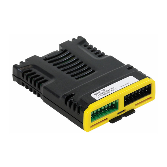
- Page 21 Figure 2-3 Example MiS210 carton label 3682 2143 MiS2 0 Serial No: 8000001001 F/W: V01.00.00.32 LISTED Model No : 8240000021100 E171230 Designed in UK. Made in UK. Figure 2-4 Example of MiS250 product label MiS250 82700000021500 S/N:8988875011 2143 S/N:8988875011 LISTED E171230 Figure 2-5 Example of MiS250 carton label 3682...
- Page 22 • MiS2x0 Installation Sheet (0478-0515). • STO Cable (CT Part Number 5321-0021) only applicable for MiS250 Connect is downloadable from the Nidec Control Techniques Ltd. website. • For MiS2x0 Firmware V01.01.00.34 a minimum Connect version of 2.17.0 is required •...
- Page 23 Technical Safety Features The overall architecture is configured as follows: [Sensor] [PES] [Actuator] Figure 3-1 Overall Architecture Sensor Actuator Dual scanning of every input and cross-checking diagnosis For the MiS210 Safety Module this is shown below in the top level architecture, showing the inputs and the outputs.
- Page 24 • When using several sensors with different functions (e.g. position indicator, access door plus speed recording) for a safety system, these must be included as an inline circuit in any technical safety assessment of the complete system. • Due compliance with safety specifications and EMC directives is mandatory WARNING •...
- Page 25 3.1.1 Diagnostic coverage for inputs The MiS2x0 Safety Module has four paired inputs, each input comprises of two input lines, input A and B (paired). The four paired lines are continuously read by the MiS2x0 Safety Module to determine the state of each input pair. Table 3-1 Local digital input diagnostics - default MEASURE COMMENT...
- Page 26 • For a technical safety assessment of the input subsystem, manufacturer's data (MTTFd, FIT figures etc.) need to be incorporated. • The DC figures quoted in Table 3-1 and Table 3-2 need to be applied in a conservative manner, and the information in the comments section need to be WARNING accounted for in the safety system.
- Page 27 • Tests should be carried out at regular intervals. E.g. at the start of every shift or once a week as deemed necessary. In any event a test must be carried out at least once every year. • Any PSU powering equipment that is connected to the MiS2x0 Safety Module must WARNING be PELV or SELV and referenced to the drive 0 V, to guarantee the voltage does not exceed 60 V under working or fault condition.
- Page 28 Table 3-4 Local encoders only Primary Encoder Secondary Encoder Achievable Type Location Type Location Safe EnDat 2.2 Channel 1 EnDat 2.2 Channel 1 Channel 1 Sin Cos Channel 1 Channel 1 EnDat 2.2 Channel 1 Channel 2 EnDat 2.2 Channel 1 Channel 2 EnDat 2.2 Channel 1...
- Page 29 • If Encoder Snooping is required on Digitax HD, then the Drive Firmware needs to be V01.23.00 or greater • Firmware V01.02.00: When using encoders, at least one instance of SS1, SS2, SLS, SOS, SLA, SSM, SDM, SLP, SDI, SBC, is required for encoder diagnostics to be WARNING executed.
- Page 30 The differential amplitude of the AB encoder Loss of both signals will cause a failure. signals is measured. The speed evaluation uses both inputs to Loss of one signal, will result in the reported determine the speed and direction of the speed being zero, one or minus one (average of equipment to which the encoder is attached.
- Page 31 Table 3-8 Encoder specific tests ENDAT SAFE Test Name Description ENDAT 2.2 Check trigonometric invariance via Trigonometric Analog Test encoder signal monitoring. One error counter based on simultaneous Digital Counter Test changes for Sin and Cos signal at the same sample. One packet flag is provided in order to Transfer Test guarantee the transfer of data between...
- Page 32 3.2.2 Encoder Mathematics The MiS2x0 Safety Module provides safety functions that may require position, speed and/or acceleration information from a variety of encoders. The encoder interface is provided by the microcontroller embedded within the MiS2x0 Safety Module. The Microcontroller is configured with information from the user when the MiS2x0 Safety Module is configured using Connect.
- Page 33 These encoders may provide either relative position or absolute position. The MiS2x0 Safety Module has no knowledge of how the encoder data / system is configured in terms of absolute or relative position. The system designer must ensure that the design accommodates the mode of operation appropriately by the selection of the correct encoder and the design of the MSFs.
- Page 34 3.2.2.4 Use of encoders in absolute measurement systems The MiS2x0 Safety Module includes motion safety functions that require position information. To achieve this the encoder and system design should comply with the following statements: 1. For position measurement the range of the encoder must encompasses the full range of movement of the equipment.
- Page 35 NOTE • Excessive Transmission Delay has a detrimental effect on the MiS2x0 Safety Module's ability to recover the data from the encoder. • The conversion time for the encoder needs to be taken into account when selecting the encoder to be used. 3.2.4 Local encoder interface (EnDat 2.2, Safe EnDat 2.2 and SSI) The MiS2x0 Safety Module can receive data from EnDat2.2, Safe EnDat2.2 or SSI via its front panel...
- Page 36 3.2.5 Cable attenuation (EnDat 2.2, Safe EnDat 2.2 and SSI) The attenuation characteristics of the cable reduces the amplitude of the high frequency components of the transmitted data. This has the effect of rounding the edges of the data signals and reducing the amplitude of the signals that represent alternating 1 s and 0 s.
- Page 37 Systems with gearing between the two encoders: In this example we will look at a system which contains a gearbox with a ratio other than 1:1 to demonstrate the setup of the MiS2x0 dual encoder feature. The primary encoder is mounted on the motor shaft which directly drives the input shaft of a gear box.
- Page 38 4. Shared memory access Manages the communications via the Drive shared memory interface. A variety of protocols and error detection mechanisms are implemented in software, providing safe and secure communication. Via this interface the MiS2x0 Safety Module can gain access to an attached network and make use of safety protocols.
- Page 39 The MiS2x0 Safety Module runs a substantial amount of self-test at both power on and continuously. The complete self-test suite is completed every 16ms. When the MiS2x0 Safety Module enters the commissioning testing state it has a time limit placed on it to prevent the unit being used in a "test"...
- Page 40 3.4.1 Networks The response time of network communications cannot be given as it will depend upon the specific network in question, size, loading etc. The MiS2x0 Safety Module with CIP Safety™ must be used only with supported onboard Ethernet firmware versions. The MiS2x0 Safety Module firmware and onboard Ethernet firmware require matching CIP Product Revision Numbers.
- Page 41 ® ® EtherCAT and Safety over EtherCAT are registered trademarks and patented technologies, licensed by Beckhoff Automation Gmbh, Germany ™ ™ EtherNet/IP and CIP Safety are trademarks of ODVA, Inc. MiS210 and MiS250 Installation and Operating manual...
- Page 42 Installation General installation notes Always follow the safety instructions during installation. The module must be installed in an IP54 or greater rated enclosure. Route all signal cables separately for activation of digital inputs and contact monitoring purposes. In all cases separate Non ELV voltages from ELV, SELV and PELV lines, if these voltages are being used in conjunction with this application.
- Page 43 • Refer to the drive manual for details on power cabling routing and protection. • Always use shielded cabling when connecting position/speed sensors. The cable used to transmit signals must be compatible with the RS-485 standard (twisted pair wiring). WARNING •...
- Page 44 4.2.2 Physical connection Place the front of the MiS210 Safety Module under the locating clip on the drive and then push down the blade, refer to MiS210 and MiS250 Safety Module Installation Sheet (0478-0515-03). Figure 4-1 MiS210 Safety Module fitted to an M700 4.2.3 MiS250 on M750, M751 and M753 On these drives there are 2 option module slots available, and the MiS250 Safety Module can only...
- Page 45 4.2.4 Physical connection of MiS250 Place the front of the MiS250 Safety Module under the locating clip on the drive and then push down, refer to MiS210 and MiS250 Safety Module Installation Sheet (0478-0515-03). Figure 4-2 MiS250 Safety Module Fitted to a Digitax HD Connection of Digital IO The diagram below shows the digital IO connector for the MiS2x0 Safety Module.
- Page 46 The MiS2x0 Safety Module Inputs and Outputs are classified in IEC 61800-3 2004 +A1:2012 Table 12 as "Ports for process measurement control lines Auxiliary DC Power ports below 60 V" and are configured using Connect. Approved OSSD outputs can be connected without restriction to the inputs.
- Page 47 Figure 4-5 MiS2x0 single input Pair, with pulse checking Sensor switches MiS210 Pulsed Pulsed Output Input 1A Output Signal Switch A Condi oning and Processing Input 1B Switch B The shield of the cable is not shown, for clarity see section 4.1. If multiple input pairs are required they are wired in the same manner.
- Page 48 Figure 4-7 Single output on MiS250 +24 V MiS250 - Outputs Main Control Switch Monitor Signal Condi oning and Processing Output A User Load Switch Control Monitor Output B Switch Control Monitor The shield of the cable is not shown, for clarity see section 4.1. If both outputs are required they are wired in the same manner.
- Page 49 Connection of encoder(s) and encoder power supplies The MiS2x0 Safety Module has four possible encoder connections, two on the host drive (A and B) and two on the front panel (1 and 2). Only certain combinations of encoder are possible, and these can be seen in section 3.2 •...
- Page 50 Table 4-1 Encoder power supply values 15 V Voltage Setting Voltage 4.8 V 5.15 V 5.6 V 7.6 V 8.2 V 8.7 V 13.9 V 15 V 16.1 V Current (Max) 250 mA 250 mA 200 mA The MiS2x0 Safety Module checks the encoder supplies that are in use and uses the following limits. Table 4-2 Encoder power supply monitoring limits Voltage Lower Limit...
- Page 51 Figure 4-9 Connection of encoders MiS210 and MiS250 Installation and Operating manual...
- Page 52 Cables If an encoder is used on the drive then depending upon the SIL needed by the application it may be necessary to monitor this power supply. The power supply can be monitored by connecting it to the Local Encoder Connector, as detailed in section 4.4.1. Figure 4-10 Encoder power supply splitter If a Sin Cos EnDat 2.1 encoder or a Hiperface with Sin Cos encoder is used on the drive, then these types of encoder cannot by snooped by the MiS2x0 Safety Module, however the Sin Cos signals can...
- Page 53 NOTE • The MiS2x0 Safety Module does not interpolate the Sin-Cos signals so only basic relative position is available. • The Encoder Power Supply Splitter with Sin Cos CAN NOT be used to gain a higher SIL rating with a single encoder unless indicated in the encoder suppliers manual. Figure 4-12 Digitax HD STO cable When using a Digitax HD Drive with a MiS250 there is no direct connection to the drive STO from the Safety Module, thus a STO Cable is supplied with the MiS250 to allow the user to connect a MiS250...
- Page 54 Connect Configuration Tool Introduction Connect screen images When using Connect each page has context sensitive help to guide the user in setting up the function. The context help in Connect is to aid the user, however the information detailed in this Safety Manual is the Master.
- Page 55 5.1.1.1 Network Profiles Connect provides some Profiles and when selected makes the appropriate connections. The "StoWiredMiS210" profile connects a Safe Boolean Hardware Input Block to the Safe Torque Off block. The corresponding MiS250 profile uses the Safe Boolean Hardware Outputs (SHOS) block instead of the Safe Torque Off block and the Safe Output 1 on the MIS250 would need to be wired to the Drive STO connection.
- Page 56 Figure 5-3 Connect StoWiredMiS210 profile Safe Torque Off (STO) Safe Boolean Hardware Inputs (SHIS) Command Source Input processing (x4) Input 1 Value Input Discrepancy Time (x4) Averagin g Input 2 Value Filter Equivalen ce Input Mode (x4) Discrepancy Averagin g Input 3 Value Timer Filter...
- Page 57 5.1.3 System The following shows the Reset screen, this covers the System Reset to start the MSFs and the Peripheral Fault Reset to acknowledge and clear Peripheral Faults. Both are fully detailed in section 8.1 and section 9.1. NOTE The System Start and Auto Reset attributes are not shared with other functionality and if required will need to be explicitly selected.
- Page 58 5.1.4 Functions Each MSF available has its own screen and parameters to set, the one shown below is for STO. To select a MSF you click on its symbol and this opens the options for the selected function. Each of the MSF menus is described in detail in section 8 giving state diagram, settable parameters, and timing diagrams.
- Page 59 Figure 5-7 Connect hardware input screen MiS210 and MiS250 Installation and Operating manual...
- Page 60 Figure 5-8 Connect non safe input screen Figure 5-9 Connect network input screen MiS210 and MiS250 Installation and Operating manual...
- Page 61 5.1.6 Outputs The following shows the 2 Hardware Outputs which are fully detailed in section 8.27 Safe Boolean Hardware Outputs, SHOS, the 16 Non Safe Outputs which are fully detailed in section 8.36 Non-Safe Boolean Output, BOS and the Network outs which are fully detailed in section 8.29 Safe Boolean Network Outputs, SNOS and section 8.31 Safe Integer Network Outputs, SINOS.
- Page 62 Figure 5-11 Connect non-safe output screen Figure 5-12 Connect network output screen MiS210 and MiS250 Installation and Operating manual...
- Page 63 5.1.7 Scope The following shows the Scope Settings screen, this allows certain outputs from the safety configuration to be mapped to the onboard scope as detailed in section 8.4. Figure 5-13 Connect scope screen MiS210 and MiS250 Installation and Operating manual...
- Page 64 Configuration - Introduction The MiS2x0 Safety Module is a safety controller designed to be attached to a drive as a plug-in module. MiS2x0 Safety Module is safety network capable and can communicate with a single safety ™ device that is either a CIP Safety originator or a FSoE Master.
- Page 65 5.2.1 Connecting and configuring individual function blocks To allow the user to make interconnections between function blocks all "Function Outputs" have one or more connection points and all "Function Inputs" have an input selector that is used to select where the function input comes from. Function blocks also have attributes that are set at design time in Connect.
- Page 66 5.2.3 Motion safety functions Motion Safety Functions (MSF) are Function blocks which are designed to Safely monitor the Motion of a single machine axis which will usually be the axis controlled by the drive hosting the MiS2x0 Safety Module. Other utility functions are also provided such as a software emergency stop function and simple Boolean gate functions.
- Page 67 5.2.4 Diagnostic codes Some Motion Safety Functions produce diagnostic codes, and these are individually detailed in the sub section for each function, see section 8. Each diagnostic code is 16 bits in length and the top nibble is a bit field with 2 flags and a 2-bit code, the lower 12 bits (11-0) are function dependent. Bit Number Value Description...
- Page 68 5.2.6 Safety configuration system data types The following data types will be supported by the MiS2x0 Safety Module. Ordinary (non-safe) types are a subset of those defined in IEC 61131 part 3. Type Name Description This safe Boolean type is accepted by safety function safe inputs and is produced as the safe output of safety functions.
- Page 69 Start Up The MiS2x0 Safety Module has 3 modes of operation, IDLE, OPERATING and CONFIGURING and 5 states, STANDBY, EXECUTING, FAILURE and COMMISSIONING (which has 2 sub states TESTING and DOWNLOAD). These are shown in the diagram below. (Testing State is referred to as Test-Comm-On in the Safety State parameter of the Module Menu as additional communications are used to report diagnostics) The MiS2x0 Safety Module is supplied with no configuration, so when connected and powered up as...
- Page 70 There are a number of failures that are deemed to be "Peripheral Faults", if after a power on when the previous mode was Operating/Executing and the last fault was a "Peripheral Fault" and the user configuration is set to allow Peripheral Fault to be Reset then then MiS2x0 will return to Operating/ Executing but will wait for a fault acknowledge before running the MSFs.
- Page 71 Validation Overview It is the user's responsibility to visually ensure that all configuration data was downloaded correctly. This includes the checking of the signature of the transferred data, and the actual configuration. This is the Validation step of the configuration. A report is produced by Connect called the Sign-Off report, to assist users in the validation of their safety system.
- Page 72 Figure 7-2 Sign-Off report sections Declaration The final section of the Sign Off Report is the Declaration which provides an area for the signature of the Safety Engineer who designed the system and records the username, date and time of the reports generation.
- Page 73 Motion Safety Function Details Encoder setup This section provides set up and indication for the two encoder inputs that provide the kinematic information to the MiS2x0 Safety Module, these values can be set using Connect in the Screen described in section 5.1.2. There are 2 encoder channels the Primary Channel supplies the kinematic information to any Motion Safety Function (MSF) that needs it, and the Secondary Channel can provide encoder redundancy to increase the system SIL.
- Page 74 Monitoring voltage for an external encoder power supply connected to the MiS2x0 Safety Module’s Encoder PSU Input pin External Supply 0: External Encoder PSU Monitoring OFF Voltage Monitoring 1: 5 V Monitoring 2: 8 V Monitoring 3: 15 V Monitoring ²...
- Page 75 Encoder type connected to the channel; the code numbers are those used in the drive but not all are supported by the safety module 0: AB (Direct to MiS2x0) 1: FD (Not Supported) 2: FR (Not Supported) 3: AB Servo (A&B channels direct to MiS2x0 only, UVW Channels not used) 4: FD Servo (Not Supported) 5: FR Servo (Not Supported) 6: SC (Direct to MiS2x0)
- Page 76 Encoder type connected to the channel; the code numbers are those used in the drive but not all are supported by the safety module 0: AB (Direct to MiS2x0) 1: FD (Not Supported) 2: FR (Not Supported) 3: AB Servo (A&B channels direct to MiS2x0 only, UVW Channels not used) 4: FD Servo (Not Supported) 5: FR Servo (Not Supported) 6: SC (Direct to MiS2x0)
- Page 77 Value that will provide the reset source for system wide alarms and by default will be shared by the resets for each MSF that requires one. A rising edge on the selected value will cause the system state machine to attempt to leave its "Wait for Reset" state providing the cause of the system alarm has cleared.
- Page 78 System alarms Problems with any of the following will raise a system alarm: • Drive Shared Memory / Brown Out • Safety Network (if configured for use) • Encoders (if configured for use) • Inputs (if configured for use) • Datum Problems A System Alarm will be held until the system is reset (either manually or automatically according to the configuration).
- Page 79 Figure 8-1 Reset state machine Ready Transient 8001 Legend: Priority (1 highest) System_Error = TRUE Wait for Wait for PERIPHERAL Start_Reset = FALSE SYSTEM RESET RESET 8002 8004 Start_Reset = TRUE System_Error = FALSE System_Reset Rising Edge Condition AND Auto_Reset = TRUE AND RunMSF Previously Reached = TRUE Condition AND Auto_Reset = TRUE AND...
- Page 80 The SCID contains the following details: • Safety Configuration 32bit CRC (SCCRC) • Safety Configuration Time/Date Stamp (SCTS) This is composed of a 32-bit (4bytes) signed value in ms, which in the PLC can be set from 0 to 23 h 59 m 59 s 999 ms (0x00000000 - 0x05265BFF) and a 16-bit (2bytes) date stamp, which is the number of days since 1/1/1972.
- Page 81 Originator ID (OUNID) On output devices an OCPUNID must be stored in the Target that matches the OUNID of the PLC to ensure that only one originator can change device outputs. In the MiS2x0 Safety Module this is set to the OUNID defined in the configuration.
- Page 82 In the Communication tab, set the path to be the MiS2x0 Safety Module. Also tick the ‘Connected’ box. Once the program is downloaded and the PLC set to run, the Monitor Tags tab of the controller tags tab will display the Exception status. The Manufacturer Specific alarm is bit 2 of the exception status.
- Page 83 RPI and timeout multiplier settings The MiS2x0 Safety Module does not support RPI settings less than 10 ms. Further to this, if an RPI setting of less than 20 ms is required, then the Timeout multiplier must be set to 2 or greater. NOTE If a Network topology does not allow these minimum values to be set, the PLC values must be set to values that can support the topology, or the topology must be changed to support the system...
- Page 84 Configuration ownership For the MiS2x0 Safety Module the configuration is downloaded from Connect and thereby owned by Connect. As far as the safety network is concerned the drive (FSoE slave device) is pre-configured with one out of a set of eight different fixed network I/O configurations referenced by a "module ID". In addition to the "module ID", the MiS2x0 will have been configured (by Connect) with a FSoE "Slave Address".
- Page 85 If using TwinCAT™ this is normally done automatically via the slots pane like so: If for some reason this is not automatic, the user will need to copy across the matching configuration from the right pane to the left pane. Safety (FSoE) network setup The FSoE Safety logic device (also known as Safety Master) in the Safety network will also need to be configured with values known as the Safety parameters that match the slave configuration.
- Page 86 If using TwinSAFE this is normally configured via the Safety Parameters and connection panes like In addition, the FSoE Slave Address needs to be set. In TwinSAFE this is automatically read from the slave: Terminology Safe data passed from the Safety Master to the MiS2x0 Safety Module is referred to as outputs by the FSoE configuration tools.
- Page 87 8.3.3 Network parameters Configuring a No Alarms Present Flag An alarm not present flag can be constructed by using a SAFEBOOL TRUE constant and connecting it directly to any SNOS output bit. If there is no alarm the corresponding bit received by the PLC will be true, if an alarm occurs the bit will be false.
- Page 88 Scope Access Name Description Channel 1 Source Source for 1 scope channel Channel 2 Source Source for 2 scope channel Channel 3 Source Source for 3 scope channel Channel 4 Source Source for 4 scope channel Channel 1 Divisor A power of 2 divisor for Scope Output 1 Channel 2 Divisor A power of 2 divisor for Scope Output 2 Channel 3 Divisor...
- Page 89 Standards: ISO 13849-1: 2023 6.2 General safety principles, Idle current 6.2 Error detection for category 3 and 4 Number of Instances: 8 Name Description Value that will provide the Channel A input signal. 0.000: Default (Illegal will cause a configuration error, this must be set by the user) Numeric ID: for a valid Output Connector from another block Channel A Source Value of Source Selected...
- Page 90 Figure 8-3 SEQV State machine MiS210 and MiS250 Installation and Operating manual...
- Page 91 Figure 8-4 SEQV Safe Equivalent timing diagram for auto reset mode turned OFF 0x8002 0xC004 0xC003 0x8003 0x8002 0x8005 0x8000 0x8002 0xC004 0xC002 0xC004 0xC003 0xC002 0xC004 0xC401 0x8004 0x8002 0x8005 0x8000 0x8003 0x8004 0x8002 transient 0x8001 Start-up MiS210 and MiS250 Installation and Operating manual...
- Page 92 Figure 8-5 SEQV Safe Equivalent timing diagram for auto reset mode turned ON 0x8002 0xC004 0xC003 0xC501 0x8005 0x8000 0x8002 0xC004 0xC501 0x8005 0x8000 0x8002 0xC004 0xC401 0x8004 0x8002 0x8004 0x80020 0x8003 0x8002 0x8004 0x8002 transient 0x8001 Start-up MiS210 and MiS250 Installation and Operating manual...
- Page 93 DIAGNOSTIC ERRORS – Information for the User Code State Description Discrepancy between Channel A and Channel B exceeded time limit. “x” indicates in which state error occurred. Discrepancy In this state: “Demand” = FALSE, “Error” = TRUE 0xCx01 Timeout 0xC301 – discrepancy during engagement (Chan A = FALSE, Chan B = TRUE) 0xC401 –...
- Page 94 Safe Not Equivalent, SNEQV This function converts two antivalent SAFEBOOL inputs into one SAFEBOOL output. Initially "Channel A" input needs to be set to FALSE and "Channel B" to TRUE at the start-up, otherwise an error state will be triggered. Then when "Channel A" input is set to TRUE and "Channel B" to FALSE (Active Input States) within Discrepancy Time limit the function will enter "Operational"...
- Page 95 Name Description Value that will provide the Channel A input signal. 0.000: Default (Illegal will cause a configuration error, this must be set by the user) Channel A Numeric ID: for a valid Output Connector from another block Source Value of Source Selected TRUE: the meaning of the signal depends on the system.
- Page 96 Figure 8-7 SNEQV State Machine MiS210 and MiS250 Installation and Operating manual...
- Page 97 Figure 8-8 SNEQV Safe Not Equivalent timing diagram for auto reset mode turned OFF 0x8002 0xC004 0xC003 0xC301 0x8003 0x8002 0x8005 0x8000 0x8002 0xC004 0xC002 0xC004 0xC003 0xC002 0xC004 0xC401 0x8004 0x8002 0x8005 0x8000 0x8003 0x8004 0x8002 transient 0x8001 Start-up MiS210 and MiS250 Installation and Operating manual...
- Page 98 Figure 8-9 SNEQV Safe Not Equivalent timing diagram for auto reset mode turned ON 0x8002 0xC004 0xC003 0xC501 0x8005 0x8000 0x8002 0xC004 0xC501 0x8005 0x8000 0x8002 0xC004 0xC401 0x8004 0x8002 0x8004 0x80020 0x8003 0x8002 0x8004 0x8002 transient 0x8001 Start-up MiS210 and MiS250 Installation and Operating manual...
- Page 99 DIAGNOSTIC ERRORS – Information for the User Code State Description Discrepancy between Channel A and Channel B exceeded time limit. "X" indicates in which state error occurred. Discrepancy In this state: "Demand" = FALSE, "Error" = TRUE 0xCx01 Timeout 0xC301 - discrepancy during engagement (Chan A = FALSE, Chan B = FALSE) 0xC401 - discrepancy during engagement (Chan A = TRUE, Chan B = TRUE) 0xC501 - discrepancy during disengagement "Channel A"...
- Page 100 Safe Emergency Stop, SES This function tests its single safe input for its state, provides reset functionality and sets the output accordingly. It supports a full manual reset and can be used without other safety logic functions where the MiS2x0 Safety Module is acting as safety controller. With the STO function it provides the functionality to support an emergency switch off (Emergency Stop Category 0).
- Page 101 Figure 8-10 SES Diagrammatic representation of the Safe Emergency Stop function Safe Emergency Stop (SES) Command Source Demand Start Reset Flag Auto Reset Error Flag Diagnostic Code Activate Reset Source Standards: EN 418: 1992 3. Definitions 4.1.12 ... Resetting the control device shall not by itself cause a restart command. ISO 13849-1: 2023 5.2.2.3 Manual reset function ISO 12100-2: 2003...
- Page 102 Name Description Reset behaviour at System Start OFF: No special reset behaviour at start up (a reset signal is required at start up) Start Reset ON: One-time automatic reset of the function at start up only A risk assessment on the system must take place and justification provided in the system documentation before this feature is used.
- Page 103 Figure 8-11 SES State Machine MiS210 and MiS250 Installation and Operating manual...
- Page 104 Figure 8-12 SES timing diagram with Start Reset OFF and Auto Reset OFF, also shows normal Reset error (0xC002) 0x8000 0x8005 0x8004 0x8005 0xC002 0x8004 0x8004 0x8000 0x8000 0x8005 0x8004 0x8005 0x8004 0x8000 0x8000 0x8003 0x8002 Start-up 0x8001 transient MiS210 and MiS250 Installation and Operating manual...
- Page 105 Figure 8-13 SES timing diagram with Start Reset ON, also shows normal Reset error (0xC002) 0x8000 0x8005 0x8004 0x8005 0xC002 0x8004 0x8004 0x8000 0x8000 0x8005 0x8004 0x8005 0x8004 0x8000 0x8000 0x8000 Start-up 0x8001 transient MiS210 and MiS250 Installation and Operating manual...
- Page 106 Figure 8-14 SES Timing Diagram with Auto Reset ON, also shows First Reset error (0xC001) 0x8000 0x8004 0x8000 0x8004 0x8000 0x8000 0x8003 0x8002 0x8003 0x8002 0x8003 0xC001 0x8002 0x8002 Start-up transient 0x8001 MiS210 and MiS250 Installation and Operating manual...
- Page 107 DIAGNOSTIC ERRORS – Information for the User Code State Description During wait for first reset, input connected to "Reset Source" signal is TRUE when a Reset Error 0xC001 rising edge is detected on the input connected to "Command Source". (first reset) In this state: "Demand"...
- Page 108 Safe Stop, SS The purpose of this function is to monitor the slowdown of the host drive and once the drive is stopped or a given time has been exceeded set its demand output to FALSE. It does not provide any form of control for the drive stop however it does provide an output (Stop Request) which is available to be used to initiate (but not control) the stop when the functions safe input goes FALSE.
- Page 109 Time Mode: The function monitors the slow down to zero speed using an adjustable time "Stop Time". If the envelope is crossed by the speed magnitude the function goes to its error state and sets its "Demand" to FALSE immediately. In addition, if the axis is detected as accelerating the function moves to the error state immediately.
- Page 110 Figure 8-17 Diagrammatic representation of the Safe Stop function Primary Encoder POSITION SPEED Safe Stop (SS) Command Source Stop Mode Demand Stop Deceleration Dwell Time Stop Request Stop Time Zero Speed Threshold Speed Control Tolerance Generate MSF Alarms Flag Error Reset Source Flag Diagnostic Code...
- Page 111 Name Description Value controls whether the function monitors a stop or not. 0.000: Default (illegal will cause a configuration error; this must be set by the user) Numeric ID: for a valid Output Connector from another block Command Value of Source Selected Source TRUE: The function is NOT monitoring a stop.
- Page 112 Name Description Diagnostic Code Diagnostic Fault Code, visible in Connect in Test Mode (see separate table) This parameter is used to activate the function. Connect will set this value to TRUE when an MSF is selected. Activate TRUE: function will be executed FALSE: function is deactivated.
- Page 113 Figure 8-19 Timing Diagram showing normal and breached ramp mode envelopes and reset behaviour 0x8000 0x8000 0x8004 0xC003 0xC001 0x8004 0xC003 Reset error 0xC002 0xC001 0xC001 0x8003 0x8000 0x8004 0x8003 0x8003 0x8003 0x8000 0x8000 0x8000 transient 0x8001 Start-up Speed magnitude MiS210 and MiS250 Installation and Operating manual...
- Page 114 DIAGNOSTIC ERRORS – Information for the User Code State Description Occurs when the axis speed breaches the slowdown envelope or exceeds the zero- 0xC001 Stop Failed speed threshold value while the input is FALSE. In this state: "Demand" = FALSE Occurs if the reset signal is high when the C001 error clears.
- Page 115 8.8.1 Safe Stop 1, SS1 For the Safe Stop 1 functionality Connect automatically configures a connection between the SS and the STO functions. For a full SS1 implementation SES should also be used as the input to this block. This function uses the Connect STO function, so this means that this SS1 is to control the drive that the MiS210 is fitted on via the blade connection.
- Page 116 All of the Selectors, Attributes and Outputs related to the SS and STO MSFs are available to be set up for this block within Connect, with the exception of those shown on the diagram above as being specifically configured by Connect. All of the Errors and Alarms raised by the SS MSF are applicable so if an Alarm is raised by SS due to an envelope breach, all of the Safe Outputs will go Safe straight away.
- Page 117 All of the Selectors, Attributes and Outputs related to the SS and SOS MSFs are available to be set up for this block within Connect, with the exception of those shown on the diagram above as being specifically configured by Connect. All of the Errors and Alarms raised by SS and SOS MSFs are applicable so if an Alarm is raised by SS or SOS due to an envelope breach, all of the Safe Outputs will go Safe straight away.
- Page 118 Zero speed monitoring: is on if the Zero Speed Command Source is FALSE, (Speed Limit Command Source is ignored). Zero speed monitoring has two modes, the simplest (Speed Mode) checks that the axis speed is below the Zero Speed Threshold and if it is NOT, sets all its outputs to FALSE and enters a latched error state, it will allow the axis to creep and so should not be used if this is a risk.
- Page 119 Figure 8-24 Speed Limit Monitoring Speed Limit Safe Speed exceeded Time - Speed Limit Immediate Mode: causes the function to monitor which ever threshold (Zero or Speed Limit) is active immediately allowing no time for the axis to slow down. This mode should be used if the machine control system will slow the machine to the appropriate speed before requesting speed monitoring.
- Page 120 Figure 8-26 Rate Mode Speed Monitoring Envelope If an envelope breached (speed plot goes through The speed is not monitored during the either red line) then: Demand = false dwell segments Error = true Normal For state codes see Diagnos c Code table running Speed at Slope set by...
- Page 121 Time Mode: causes the function to monitor which ever threshold (Zero or Speed Limit) is active allowing time for the axis to slow down to the selected threshold by providing an adjustable slow down time. This mode should be used if the machine control system will not slow the machine to the appropriate speed before requesting speed monitoring and the deceleration rate is unknown or variable, and only a maximum time can be given.
- Page 122 Errors and Reset: If an error occurs the function will set "Demand" to FALSE and will remain in this state until the source of the error clears. The function must then be reset by means of a rising edge applied to the reset input;...
- Page 123 ISO 13849-1: 2023 5.2.2.3 Manual reset function ISO 12100-2: 2003 4.11.4: Restart following power failure/spontaneous restart Number of Instances: 4 Name Description Value controls whether the function monitors for a safe speed or not. 0.000: Default (illegal will cause a configuration error; this must be set by the user) 0.001: Disabled, turns off Speed Limit Monitoring, if this input is disabled, then "Zero Speed Command Source"...
- Page 124 Name Description Value that will provide the reset source, typically it will be System Reset but may be connected to any input to control the Reset. 0.002: Default, indicating that the function reset should share the System Reset input Numeric ID: From a Non-Safe Boolean Input (BIS) or from a SAFEBOOL if it is also connected Reset Source to another Safe Output.
- Page 125 Name Description Speed Limit Dwell Amount of time to be inserted into the Rate Envelope before Deceleration to a given limit starts Time to be monitored. (RATE MODE Time in ms ONLY) Zero Speed Dwell Amount of time in milliseconds to be inserted into the Rate Envelope before Deceleration to Time zero starts to be monitored.
- Page 126 Figure 8-31 State Machine Legend: Output state boundaries Priority (1 highest) Condition AND Speed limit envelope exceeded Speed Limit Command In = true AND Zero Speed Command In = true Speed under speed limit envelope Condition AND Reset = true (rising edge) Speed meets zero speed condition Reset = true AND Speed under Active Threshold Zero Speed Command In = false (Speed Limit = don t care)
- Page 127 Figure 8-32 Timing Diagram - Immediate mode 0xC004 0xC031 0x8033 0xC004 0xC003 0xC031 0xC003 0xC032 0xC032 0x8034 0x8034 0x8034 0x8000 0x8000 0x8000 0x8034 0xC004 0xC032 0x8034 0x8034 0x8033 0xC004 0xC031 0xC031 0xC031 0xC031 0x8033 0x8001 transient Speed Start-up Magnitude MiS210 and MiS250 Installation and Operating manual...
- Page 128 Figure 8-33 Timing Diagram - Timed mode 0xC004 0xC031 0x8033 0x8013 0xC004 0xC003 0xC032 0xC032 0xC032 0x8034 0x8034 0x8034 0x8014 0x8000 0x8000 0x8000 0x8034 0x8014 0xC004 0xC032 0x8034 0x8014 0x8033 0x8013 0xC004 0xC031 0xC031 0xC031 0xC031 0x8013 0x8001 transient Speed Start-up Magnitude MiS210 and MiS250 Installation and Operating manual...
- Page 129 Figure 8-34 Timing Diagram - Rate mode 0xC004 0xC031 0x8033 0x8033 0x8033 0x8033 0x8023 0x8013 0x8034 0x8034 0x8034 0x8024 0x8014 0x8000 0x8000 0x8034 0x8024 0x8014 0xC004 0xC032 0x8034 0x8024 0x8014 0x8033 0x8023 0x8013 0xC004 0xC011 0xC011 0xC011 0x8023 0x8013 0x8001 transient Speed Start-up...
- Page 130 ERRORS THAT CAN TRIGGER ALARMS - ALL SAFE OUTPUTS GO SAFE Code State Description Occurs when the axis speed exceeds the zero-speed threshold value or if configured Zero Speed the standstill distance, whichever comes first. The X in the code is a 4bit value that 0xC0X1 Threshold can be used to determine in which envelope segment the error occurred...
- Page 131 8.10 Safe Two-Handed Control Type 3, STHC3 This function provides the two-hand control functionality according to EN 574, Section 4 Type III with additional options to disable Auto Reset and set Delayed Restart. When Auto Reset is ON and Delay Restart Time is set to zero, the function operates as standard two-hand control Type III (described in EN 574, Section 4).
- Page 132 EN13851: 2019 Clause 4, Table 1, Type III A; B; C. 5.2 Use of both hands / simultaneous actuation. 5.3 Relationship between output signal and input signals. 5.4 Completion of the output signal. 5.7 Reinitiation of the output signal. 5.8 Synchronous actuation. At least PL c (according to ISO 13849-1) or SIL 1 (according to IEC 62061) At least PL d with category 3 (according to ISO 13849-1) or SIL 2 with HFT=1 (according to IEC 62061)
- Page 133 Name Description This parameter is used to activate the function. Connect will set this value to TRUE when an MSF is selected. Activate TRUE: function will be executed FALSE: function is deactivated Figure 8-36 State Machine MiS210 and MiS250 Installation and Operating manual...
- Page 134 Figure 8-37 Auto Reset ON 0x8002 0x8000 0x8003 0x8002 0x8000 0x8002 0x8009 0x8003 0x8002 0x8005 0x8004 0x8002 0x8007 0x8008 0x8006 0x8000 0x8002 Start-up transient 0x8001 MiS210 and MiS250 Installation and Operating manual...
- Page 135 Figure 8-38 Auto Reset OFF 0x8002 0x8000 0x8004 0x8002 0x8009 0x8004 0x8002 0x800A 0x8009 0x800A 0x800B 0x800A 0x8009 0x8003 0x8002 0x8005 0x8004 0x8002 0x8007 0x8008 0x8006 0x8000 0x8002 Start-up transient 0x8001 MiS210 and MiS250 Installation and Operating manual...
- Page 136 DIAGNOSTIC ERRORS – Information for the User Code State Description Only one of the button signals was TRUE while the other was FALSE for more than 500 ms. Both Button inputs need to be FALSE to leave this error state. When the error cause is cleared and "Auto Reset"...
- Page 137 DIAGNOSTIC ERRORS – Information for the User Code State Description This state occurs after "Operational" state when "Button 2" input is set FALSE, but "Button 1" input is still TRUE. Note that it is possible to "jump" between this state, "Release Sequence Wait for Release Btn2"...
- Page 138 8.11 Safe Operating Stop, SOS This function when the Command Source is FALSE, monitors the speed of the axis and sets its output TRUE if the axis speed is below the zero-speed threshold and (optionally) if the axis is not creeping, otherwise it is set to FALSE.
- Page 139 Ensures that the motor remains stopped by resisting external forces. Number of Instances: 4 However, one is reserved for use within Safe Stop 2 Name Description Value which will request safe operating stop monitoring. 0.000: Default (Illegal will cause a configuration error, this must be set by the user) Command Numeric ID: for a valid Output Connector from another block Source...
- Page 140 Figure 8-40 State Machine Priority (1 highest) Output state boundary Stop Command In = true Stop Command In = false Zerospeed OR Standstill envelope exceeded Condition AND Zerospeed or Standstill envelope breached Monitoring condition met (at zero speed with optional standstill) Condition AND Reset In rising edge Condition...
- Page 141 Figure 8-41 Timing Diagram showing the difference between speed and position mode Timing for SOS Active position mode envelopes showing different start positions Time Active speed envelopes (both modes) Time A position mode stop error clears when the safe stop input is set to true Inputs Command...
- Page 142 ERRORS THAT CAN TRIGGER ALARMS - ALL SAFE OUTPUTS GO SAFE Code State Description In either mode the detected speed is greater that the speed specified in Zero Speed 0xC001 Speed Error Threshold or excessive creep has been detected in position mode. In this state: "Demand"...
- Page 143 Latency The time between speed samples varies in sympathy with the configured Speed Averaging Sample Time filter (See section 8.1) i.e. when a speed filter of four is selected, the two speeds samples 4 ms apart are used to determine the acceleration.
- Page 144 Figure 8-42 Visual Representation of the 4 Quadrants time time Quadrant Velocity Acceleration Name Positive Positive Positive Negative Acceleration Negative Negative Negative Positive time time Errors and Reset: If an error occurs the function will set "Demand" to FALSE and will remain in this state until the source of the error clears.
- Page 145 Standards: EN 61800-5-2:2017 4.2.3.14 Safe Speed Monitor (SLA) The SLA function prevents the motor from exceeding the specified acceleration limit. Number of Instances: 4 Name Description Value for the quadrant monitoring control signal which will request acceleration monitoring for that quadrant; alternatively monitoring can be set to always on or always off. 0.000: Default (Illegal will cause a configuration error, this must be set by the user) Command Numeric ID: for a valid Output Connector from another block...
- Page 146 Figure 8-44 State Machine X in the diagnostic code indicates state prior to alarm, Y indicates the current quadrant or in alarm state the quadrant in which the alarm was detected MiS210 and MiS250 Installation and Operating manual...
- Page 147 Figure 8-45 SLA timing diagram 8000 8023 8012 8012 8043 8003 8043 8032 8003 C513 C512 C511 8012 8003 C533 C531 8032 8023 8012 8003 C513 C511 8012 8003 8032 8003 transient 8001 Start-up Accel- Speed eration The XY fields in the diagnostic code show the values for this scenario MiS210 and MiS250 Installation and Operating manual...
- Page 148 ERRORS THAT CAN TRIGGER ALARMS - ALL SAFE OUTPUTS GO SAFE Code State Description Occurs when the axis acceleration exceeds the acceleration limit in monitored quadrant. The X in the code is a 4 bit value that can be used to determine in which state error Acceleration occurred: 1 –...
- Page 149 8.13 Safe Speed Monitoring, SSM The purpose of this function is to monitor the speed of the drive and set the output true if the axis speed is below the monitoring speed or false otherwise. Figure 8-46 Illustration of output state with axis speed Safe Speed Time Safe Speed...
- Page 150 Name Description Outputs the safety related response of the function Safe Speed FALSE: The function is not initialized, OR and the axis speed is above the safe speed value. Active TRUE: The function is initialized, and the axis speed is below or equal to the safe speed value. Speed that the function will use for its speed limit, unless it is under-ridden by the Speed Underride Input and its multiplier, if this is the case then this parameter acts as an upper limit Safe Speed...
- Page 151 Linear encoders The range is limited by physical characteristics and so cannot wrap. NOTE • It is the responsibility of the motion control system to move the axis onto the safe datum sensor and stop, a safe output is provided to signal that a datum is required (this may be connected to a non-safe output).
- Page 152 In the case of a relative encoder, a datum is required at each power up. If Go Live is enabled, when a rising edge is detected the Demand out will be set true thus signalling that the axis can move. If GoLive is disabled, the Demand out is set true immediately.
- Page 153 Figure 8-48 Diagrammatic representation of the Safe Datum function Primary Encoder POSITION SPEED Safe Datum (SDM) Safe Position Command Source Demand Zero Speed Threshold Datum Complete Timeout Go Live Source Datum Offset Values Saved at Datum Triggered, Cleared on Start up Invalidate: Invalidate Datum Datum Set Not Datumed,...
- Page 154 Name Description Provides the input to the MiS2x0 to tell it to allow the machine axis to move so as the Datum process can complete. This is an optional input, but the system designer must be made aware that once a new datum is requested, without this additional input, STO will be deactivated (or other mitigation set to TRUE) and the machine may start to move immediately.
- Page 155 Name Description This parameter is used to activate the function. Connect will set this value to TRUE when an MSF is selected. Activate TRUE: function will be executed FALSE: function is deactivated. MiS210 and MiS250 Installation and Operating manual...
- Page 156 Figure 8-49 State Machine DIAGNOSTIC ERRORS - Information for the User Code State Description 0x8000 Datumed Axis is datumed and position dependent functions run normally 0x8001 Ready Start-up transient 0x8002 Wait for Go Live Waiting for Rising Edge on Go Live before starting Datum Process Waiting to see Command input Go High at zero speed indicating 0x8003 Datuming...
- Page 157 Figure 8-50 Timing Diagram when Go Live Disabled 0x8000 0x8003 0x8004 0x8003 Ignored already datumed 0x8000 0x8003 Start-up 0x8001 Speed MiS210 and MiS250 Installation and Operating manual...
- Page 158 Figure 8-51 Timing Diagram when Go Live Enabled 0x8000 0x8003 0x8002 0x8004 0x8003 Ignored Go Live is false Ignored already datumed 0x8000 0x8003 0x8002 Start-up 0x8001 Speed MiS210 and MiS250 Installation and Operating manual...
- Page 159 8.15 Safely Limited Position, SLP The purpose of this function is to monitor the position of the axis and if it exceeds the defined envelope set the Demand to FALSE and enter an error state. There are 2 possible modes, Stopping Distances Not Calculated and Stopping Distances Calculated, where a prediction of a position breach is used instead of an actual exceed.
- Page 160 Figure 8-52 Safe Position Monitoring with and without stopping distance prediction (a square velocity profile is shown for simplicity) Position monitoring without stopping distance prediction Key:- p : axis position v : axis velocity t : time : monitoring start time : error detection time SD : stopping distance : normal pos n control...
- Page 161 Interaction with Safe Datum (SDM) When SDM is activated the following applies: When the output "Datum Complete" is FALSE, all position monitoring function primary demand outputs are set to TRUE to allow STO to be deactivated (TRUE) and motion to occur. All other position monitoring function status outputs are set to FALSE and the function diagnostic code is set to 0x8FFF (datuming).
- Page 162 Figure 8-53 Diagrammatic representation of the Safely Limited Position function Primary Encoder POSITION SPEED Safely Limited Position (SLP) Command Source Demand Lower Position Limit Safety Active Upper Position Limit Q2 Deceleration Q4 Deceleration Generate MSF Alarms Flag Error Flag Diagnostic Code Activate Reset Source MSF ALARM SYSTEM...
- Page 163 Name Description Value that will provide the reset source, typically it will be System Reset but may be connected to any input to control the Reset. 0.002: Default, indicating that the function reset should share the System Reset input Numeric ID: From a Non-Safe Boolean Input (BIS) or from a SAFEBOOL if it is also connected Reset Source to another Safe Output.
- Page 164 Figure 8-54 State Machine Ready Transient 8001 Position exceeded C001 Reset Error Wait for Reset C002 C003 Demand_Out = FALSE Safety_Active_Out =FALSE Priority (1 highest) Output state boundaries Monitoring Safety_Active_Out = TRUE Position Position Limit Command = true 8002 Demand_Out = TRUE Position Limit Command = false AND position limit not exceeded Position Limit Command = false AND...
- Page 165 Figure 8-55 Timing Diagram 0x8000 0x8000 0x8000 0x8000 0xC003 0xC001 0xC001 0xC001 0xC002 0xC001 0x8002 0x8000 0x8000 0x8000 0x8002 0x8002 0xC003 0xC001 0xC001 transient 0x8002 0x8000 0x8000 0x8000 0x8000 0x8000 0x8000 transient 0x8001 Start-up Position MiS210 and MiS250 Installation and Operating manual...
- Page 166 8.16 Safe Direction, SDI This function tests the encoder signals and sets its output to TRUE if the axis is moving in the selected direction, otherwise the output is set to FALSE. An integrator allows a configurable amount of motion in the opposite direction if required. Figure 8-56 Graph of SDI function Safe Direction Active = TRUE...
- Page 167 Figure 8-56 Graph of SDI function set for forward direction with a maximum reverse distance of 200 counts, showing that a short excursion (at time 800) in the opposite direction can be tolerated if required, and the equivalent forward motion required to clear the accumulated opposite motion. The accumulator value over time is shown as a solid red line.
- Page 168 Behaviour by cycle in priority order (behaviour is defined by the first row where the checks are TRUE) Checks Made Opposite Opposite Distance Actions Taken during Direction (as Output State Distance Accumulator Evaluation indicated by Reached after SDI Tolerance Value after (apart from setting sign of speed) Flag...
- Page 169 Holding Brake Mode: The brake will not be applied (function output to FALSE) until the axis reaches zero speed. This mode must not be used with overhauling or high inertia loads and the machine must come to a halt when no power is applied. Emergency Brake Mode: The output will go FALSE as soon the brake control input goes FALSE, an adjustable timer will prevent a reset until a given time from brake actuation.
- Page 170 Standards: BS EN 61800-5-2:2017 Section 4.2.5 This function provides a safe output signal(s) to control an external brake(s). Number of Instances: 1 Name Description Provides the command to release or apply the brake 0.000: Default (Illegal will cause a configuration error, this must be set by the user) Release Numeric ID: for a valid Output Connector from another block Command...
- Page 171 Name Description This output is normally TRUE. When the Brake Control the Contactor confirm source and the Brake Confirm do not match it is set False. If the axis fails to stop in the time prescribed in Brake Fail Time or the Brake Contactor or Brake Confirm Fails to change state either when Brake Control is applied or released, within the time prescribed by the Brake Response Time, this output and the Brake Control are set to FALSE until the function is reset.
- Page 172 Name Description Defines the maximum time between the Brake Release commanding the application of the brake and the detection of the machine speed being equal to or below the Zero Speed Threshold. (Also referred to as Brake Fail Time). If the specified response time is exceeded the function will enter an error state requiring the removal of the fault condition and a reset Fail Time before operation can continue.
- Page 173 Figure 8-59 State Machine MiS210 and MiS250 Installation and Operating manual...
- Page 174 Figure 8-60 Timing Diagram, Mode 1 0x8000 brake response time 0x8004 0x8006 Brake off signal repaired and 0x8004 correctly corrrelating (module left on) 0xC323 0xC322 brake fail time brake response time 0x8003 0x8000 brake response time 0x8004 0xC313 Axis stops later than required – (assumes module left on) 0xC311 brake...
- Page 175 Figure 8-61 Timing Diagram, Mode 2 0x8000 brake response time 0x8004 0x8006 0x8006 0x8004 0xC423 Brake off signal repaired and correctly corrrelating (module left on) 0xC422 brake response time 0x8004 brake 0x8002 fail time 0x8000 brake response time 0x8004 0xC713 brake response time Axis stops later than required –...
- Page 176 Figure 8-62 Timing Diagram, Mode 3 and 4 0x8000 brake response time 0x8004 0x8006 0x8006 0x8004 Brake 0x8005 Cooling Time 0xC323 Brake off signal repaired and correctly corrrelating (module left on) 0xC322 brake fail time 0x8003 brake response time 0x8000 brake response time 0x8004 0x8005...
- Page 177 ERRORS THAT CAN TRIGGER ALARMS - ALL SAFE OUTPUTS GO SAFE Code State Description This state can be reached in Mode = Emergency or Operational. The state is entered when the speed of the machine is not equal or less than the 0xCX11 Failed to Stop Brake Zero Speed Threshold within the required time.
- Page 178 ERRORS THAT CAN TRIGGER ALARMS - ALL SAFE OUTPUTS GO SAFE Code State Description In this state the axis has stopped, and the Unlock signal is enabled and is FALSE In this state the outputs are :- “Demand” = FALSE, 0x8006 Brake locked “Brake On and Axis Stopped”...
- Page 179 8.18 Safe OR, SOR This logic function tests its two safe inputs for their state, applies a logical OR and sets the output accordingly. Values are available to be read in Test Mode, if values are read from an activated function the current values are returned, if a read is made on a deactivated function the default value is returned.
- Page 180 8.19 Safe Not OR, SNOR This logic function tests its two safe inputs for their state, applies a logical NOR and sets the output accordingly. Values are available to be read in Test Mode, if values are read from an activated function the current values are returned, if a read is made on a deactivated function the default value is returned.
- Page 181 8.20 Safe Exclusive OR, SXOR This logic function tests its two safe inputs for their state, applies a logical XOR and sets the output accordingly. There are eight available instances of this function for the user. Each can be activated or deactivated at design time only.
- Page 182 8.21 Safe Exclusive Not OR, SXNOR This logic function tests its two safe inputs for their state, applies a logical XNOR and sets the output accordingly. Values are available to be read in Test Mode, if values are read from an activated function the current values are returned, if a read is made on a deactivated function the default value is returned.
- Page 183 8.22 Safe AND, SAND This logic function tests its two safe inputs for their state, applies a logical AND and sets the output accordingly. Values are available to be in Test Mode, if values are read from an activated function the current values are returned, if a read is made on a deactivated function the default value is returned.
- Page 184 8.23 Safe Not AND, SNAND This logic function tests its two safe inputs for their state, applies a logical NAND and sets the output accordingly. Values are available to be read in Test Mode, if values are read from an activated function the current values are returned, if a read is made on a deactivated function the default value is returned.
- Page 185 8.24 Safe 8 AND, S8AND This function tests its eight safe inputs for their state, applies a logical AND then sets the output accordingly. Some of the safe inputs can be disabled. Values are available to be read in Test Mode, if values are read from an activated function the current values are returned, if a read is made on a deactivated function the default value is returned (typically 0 or FALSE).
- Page 186 Name Description Secondary input selector that can be disabled. Selects the safety signal that needs to be ANDed with the value connected to other active input selectors. 0.000: Default (Illegal will cause a configuration error, this must be set by the user) Channel D 0.001: Disabled, input selector is disabled and acts as logical TRUE Source...
- Page 187 If an input becomes discrepant for more than the user set time an Error is generated (set to TRUE), which triggers a System Alarm (See section 9.2) which will set all of the MiS2x0 Safety Module outputs to FALSE and stop evaluation of all Logic and Output functions. This is irrespective of the state of the rest of the configuration and is because the inputs can no longer be trusted.
- Page 188 Name Description Value that will provide the reset source, typically it will be System Reset but may be connected to any input to control the Reset. 0.001: Disabled, the Auto Reset attribute must be set to on. 0.002: Default, indicating that the function reset should share the System Reset input Numeric ID: From a Non-Safe Boolean Input (BIS) or from a SAFEBOOL if it is also Reset Source connected to another Safe Output.
- Page 189 Name Description Input 4 Diagnostic Same as Above Code Indicates that the function has detected an error condition. TRUE: Error, an enabled input has been discrepant for more than the allowed time, check Error Diagnostic Codes FALSE: No Error. Diagnostic Code Diagnostic Fault Code, visible in Connect in Test Mode (see separate table) This parameter is used to activate the function.
- Page 190 Figure 8-73 Timing Diagram for input 1 (all other inputs disabled) with Auto Reset OFF, showing 3 discrepancy errors 0x9000 0xC103 0xC103 0xC102 0xC101 0x9011 0x9001 0x9000 0x9001 0x9001 0x9000 0x9000 0x9001 0xC103 0xC101 0xC103 0xC103 0xC103 0xC103 0xC101 0x9011 0x9001 0x9000 0x9001...
- Page 191 Figure 8-74 Timing Diagram for input 2 (all other inputs disabled) with Auto Reset ON, showing 3 discrepancy errors 0x9000 0xC203 0xC203 0xC202 0xC201 0x9022 0x9002 0x9000 0x9002 0x9002 0x9000 0x9000 0x9002 0xC103 0xC201 0x9022 0x9002 0x9000 0x9002 0xC201 0x9022 0x9002 0x9000 0x9002...
- Page 192 Code used in Description diagrams INPUT PAIR 1 - 0 if channel A and channel B are both ON otherwise 1 INPUT PAIR 2 - 0 if channel A and channel B are both ON otherwise 1 INPUT PAIR 3 - 0 if channel A and channel B are both ON otherwise 1 INPUT PAIR 4 - 0 if channel A and channel B are both ON otherwise 1 INPUT PAIR 1 - 1 if is discrepant but not timed out, otherwise 0 INPUT PAIR 2 - 1 if is discrepant but not timed out, otherwise 0...
- Page 193 Table 8-1 Individual Pair Diagnostic Codes Hardware Input Description 0x00800004 Input Channel A = 1 and Input Channel B = 1 0x00800104 Input Channel A = 0 and Input Channel B = 0 0x00800404 Input Channel A & B = 1 and previously were discrepant 0x00800604 Input Channel A &...
- Page 194 Figure 8-75 Diagrammatic representation of the STO function Safe Torque Off (STO) Command Source Flag Status FTS Source Flag Diagnostic Code Activate Standards: IEC 61800-5-2 4.2.2.2 Safe torque off (STO) 6. Requirements for design and development of a PDS(SR) (SIL level). IEC 60204-1 3.56 Uncontrolled Stop.
- Page 195 Figure 8-76 State Machine Legend: Priority (1 highest) ( Ctrl = true AND FTS_source = disabled) OR ( Ctrl = Ready, true AND FTS = true) Wait for Ctrl = false Command = True A001 Ctrl = true AND FTS = false Ctrl = false FTS = true Wait for...
- Page 196 Figure 8-77 Timing Diagram MiS210 and MiS250 Installation and Operating manual...
- Page 197 DIAGNOSTIC ERRORS - Information for the User Code State Description 0xA011 Initialise Transient (1 ms) at start up only. Ready, Wait for The input connected to “Command Source” is FALSE. 0xA001 “Command Drive STO circuitry prevents the motor from producing torque. Source”...
- Page 198 Figure 8-78 Diagrammatic representation of the Hardware Outputs Output hardware SAFEBOOL Hardware Outputs (SHOS) Output 1 Command Source Output 1 FTS Source Output 2 Command Source Output 2 FTS Source Flag Status Flag Diagnostic Code Activate Standards: IEC 61131-2:2007 Programmable controllers. Part 2: Equipment requirements and tests.
- Page 199 Name Description Value that can set the Hardware Output 1 to FALSE but only set it to TRUE if “Output 1 Command Source” is also TRUE. (Force to Safe - FTS). 0.001: Default, disables the input Output 1 FTS Numeric ID: for a valid Output Connector from another block Source Value of Source Selected TRUE: A normal signal (i.e.
- Page 200 Figure 8-80 Timing Diagram for Output 1 (all other outputs disabled) 0xA022 0xA023 0xA022 0xA023 0xA032 0xA022 0xA023 0xA022 0xA032 0xA023 MiS210 and MiS250 Installation and Operating manual...
- Page 201 Code used in Description diagrams OUTPUT 1 - 0 if ON (TRUE) OUTPUT 2 - 0 if ON (TRUE) Not Used Not Used OUTPUT 1 - if Forced to Safe OUTPUT 2 - if Forced to Safe Not Used Not Used DIAGNOSTIC ERRORS - Information for the User Code State...
- Page 202 8.28 Safe Boolean Network Inputs, SNIS Each instance represents a set of 4 SAFEBOOL inputs transmitted over a safety network to the MiS2x0 Safety Module, and the MiS2x0 Safety Module can handle up to 32 bits. A mode attribute allows individual bits to be turned on and off, this is represented in Connect by the drop-down box for a bit saying unassisgned.
- Page 203 Number of Instances: 8 Instance 1 - Bits 0-3 Instance 2 - Bits 4-7 Instance 3 - Bits 8-11 Instance 4 - Bits 12-15 Instance 5 - Bits 16-19 Instance 6 - Bits 20-33 Instance 7 - Bits 24-27 Instance 8 - Bits 28-31 The data from the PLC is an array of bytes (8bits) and the boolean data is interleaved with the integer data if it is being used.
- Page 204 Name Description Bit 3 Mode Same as Above This parameter is used to activate the function. Connect will set this value to true when an MSF is selected. Activate Bit 0-3 TRUE: function will be executed. FALSE: function is deactivated. 8.29 Safe Boolean Network Outputs, SNOS Each instance of this function block represents a set of 4 SAFEBOOL outputs to be transmitted over...
- Page 205 Instance 5 - Bits 16-19 Instance 6 - Bits 20-33 Instance 7 - Bits 24-27 Instance 8 - Bits 28-31 The data to the PLC is an array of bytes (8bits) and the boolean data is interleaved with the integer data if it is being used.
- Page 206 Name Description For instance 1, the value selected by parameter 004 goes to Network Byte 0 bit 3 For instance 2, the value selected by parameter 104 goes to Network Byte 0 bit 7 For instance 3, the value selected by parameter 204 goes to Network Byte 5 bit 3 For instance 4, the value selected by parameter 304 goes to Network Byte 5 bit 7 For instance 5, the value selected by parameter 404 goes to Network Byte 10 bit 3 For instance 6, the value selected by parameter 504 goes to Network Byte 10 bit 7...
- Page 207 Name Description For instance 1, the value selected by parameter 034 goes to Network Byte 0 bit 3 For instance 2, the value selected by parameter 134 goes to Network Byte 0 bit 7 For instance 3, the value selected by parameter 234 goes to Network Byte 5 bit 3 For instance 4, the value selected by parameter 334 goes to Network Byte 5 bit 7 For instance 5, the value selected by parameter 434 goes to Network Byte 10 bit 3 For instance 6, the value selected by parameter 534 goes to Network Byte 10 bit 7...
- Page 208 The diagnostic codes for output a (output b to d disabled) are listed below. Code used in Description diagrams 1 = Output a is OFF (FALSE), 0 = Output a is ON (TRUE) 1 = Output b is OFF (FALSE), 0 = Output b is ON (TRUE) 1 = Output c is OFF (FALSE), 0 = Output c is ON (TRUE) 1 = Output d is OFF (FALSE), 0 = Output d is ON (TRUE) 1 = Output a is forced to SAFE, 0 = Output a is NOT forced to SAFE...
- Page 209 8.30 Safe Integer Network Inputs, SINIS This function block represents a set of 4 SAFEINT (32 bit) inputs transmitted over a safety network to the MiS2x0 Safety Module. Each 32 bit input can be disabled, but they can still be passed in by the network.
- Page 210 Number of Instances: 1 The data from the PLC is an array of bytes (8 bits) and the boolean data is interleaved with the integer data if it is being used. 8 bits of Boolean Data (SNIS 1 & SNIS 2) 32 bits of Integer Data (SINIS Integer 1) 8 bits of Boolean Data (SNIS 3 &...
- Page 211 Name Description Integer 4 Value Bytes 16-19 to Integer 4 Value This parameter is used to activate the function. Connect will set this value to true when an MSF is selected. Activate Int 1-4 TRUE: function will be executed FALSE: function is deactivated 8.31 Safe Integer Network Outputs, SINOS This function block represents a set of 4 SAFEINT (32 bit) outputs to be transmitted over a safety...
- Page 212 Figure 8-87 SNOS Mapping Safe Network Outputs (SNOS) - Bools SNOS 1 Bit 0 Value SNOS 1 Bit 1 Value SNOS 1 Bit 2 Value PLC SINT (8 bit) Safety Input SNOS 1 Bit 3 Value Safe Network Outputs MiS2x0.SI.Data[0] SNOS 2 Bit 4 Value (SNOS) - Bools SINOS 1 Integer 1 Value (MSW MSB)
- Page 213 8.32 Safe TRUE, STIS The STIS function has no inputs, and its 10 safe outputs are always TRUE. It is intended to be used to force SAFEBOOL function inputs or Non-Safe Inputs to TRUE for testing purposes. Unless the whole function instance is deactivated the output connectors for the instance are always present even if the input is not used.
- Page 214 8.33 Safe FALSE, SFIS The SFIS function has no inputs, and its 10 safe outputs are always FALSE. It is intended to be used to force SAFEBOOL function inputs or Non-Safe Inputs to FALSE for testing purposes. Unless the whole function instance is deactivated the output connectors for the instance are always present even if the input is not used.
- Page 215 8.34 Safe Constant Integer, SCIS The SCIS function has no inputs, and its 4 safe outputs take the integer value stored in the corresponding attribute. It is intended to be used to force SAFEINT function inputs to a given value for testing purposes.
- Page 216 8.35 Non-Safe Boolean Input, BIS Each instance provides access to 4 non-safe Boolean inputs that are routed through the setup menu (see section 9.5.3). The state of each input value is updated at the start of every cycle before the motion safety functions are run.
- Page 217 Name Description The state of the associated bit parameter in the setup menu For instance 1, Parameter 17.032 maps to Parameter 91.042 Bit 2 Value For instance 2, Parameter 17.036 maps to Parameter 91.142 For instance 3, Parameter 17.040 maps to Parameter 91.242 For instance 4, Parameter 17.044 maps to Parameter 91.342 The state of the associated bit parameter in the setup menu For instance 1, Parameter 17.033 maps to Parameter 91.043...
- Page 218 Number of Instances: 4 Instance 1 – Bits 1-4 Instance 2 – Bits 5-8 Instance 3 – Bits 9-12 Instance 4 – Bits 13-16 Name Description The state of the associated bit parameter in the setup menu For instance 1, the value selected by parameter 031 goes to Parameter 17.051 Bit 1 Command For instance 2, the value selected by parameter 131 goes to Parameter 17.055 Source...
- Page 219 Diagnostics and Maintenance Diagnostic code categories The diagnostic codes provided by the MiS2x0 can be split into two categories. The first category contains the diagnostic codes provided as a result of normal operation. The second category contains those diagnostic codes that result from hardware or software execution faults. The categories are subdivided into types each resulting in a specific action taken by the MiS2x0.
- Page 220 Table 9-1 Operational diagnostics Type Source Impact on System Reset System alarm can be configured to System Alarm: - Operation of All outputs are switched off. i. Reset on power cycle, a peripheral or the Drive is The system continues running ii.
- Page 221 Internal faults Cause: - Internal Faults are those associated with the MiS2x0 hardware or the operation of the software. Faults in the hardware around the MiS2x0 processor are detected by the continuous built in self test. The processor has embedded features that allow the detection of processor hardware faults, clocks, timers, memory and processor faults and software execution faults.
- Page 222 Table 9-4 System Alarm Codes Code Message Type 0x00000134 Shared Memory Alive Counter Timed Out Network Alarm 0x00000234 Shared Memory Reports Drive Brown Out Network Alarm 0x00000334 Communications Module Error, Check Black Channel Enabled Network Alarm 0x00000434 Network Not Available see Setup Menu Parameter 028 Network Alarm 0x00000534 Shared Memory Reports Invalid Network Input Data...
- Page 223 The MSF Alarm is built up in the following way where "i" is the instance number of the MSF, so SLS instance 1 would be 160 and SLS instance 2 would be 161. For the specific alarms see the individual MSF sections within the manual.
- Page 224 Code Message Type 0x000000E3 0x000000E3 0x00000014 Internal module failure. Contact the supplier of the drive 0x00000114 0x00000214 0x00000314 0x00000024 Scheduler overrun. Configuration is too big to be ran in the 1 ms cycle time 0x00000224 Internal module failure. Contact the supplier of the drive Configuration download failed.
- Page 225 Code Message Type Read returns that a sector is empty. Normal behaviour with a new module or a factory 0x00000046 reset module 0x00000056 MODE and STATE log is 90 % full 0x00000066 MODE STATE & DATUM sector full. Power cycle drive 0x00000076 ALARM and FAULT log is full 0x00000086...
- Page 226 Code Message Type 0x000008E7 PSU 24 V self-test range error 0x000009E7 0x00000AE7 Internal module failure. Contact the supplier of the drive 0x00000BE7 0x00000CE7 Encoder 5 V range error 0x00000DE7 Encoder 8 V range error 0x00000EE7 Encoder 15 V range error 0x00000FE7 PSU 24 V range error 0x000010E7...
- Page 227 Code Message Type 0x000032F7 0x000033F7 0x000034F7 0x000035F7 0x000036F7 0x000040F7 0x000041F7 0x000042F7 0x000043F7 0x000044F7 0x000045F7 Internal module failure. Contact the supplier of the drive 0x000046F7 0x000047F7 0x000048F7 0x000049F7 0x00004AF7 0x00004BF7 0x00004CF7 0x00004DF7 0x00004EF7 0x00004FF7 Can occur if safe outputs are short circuited. 0x000050F7 Internal module failure.
- Page 228 Safety DLL fault list Table 9-7 Safety DLL fault codes Code Message FUNCTIONS 0x0FFFFFFE Access Control – NULL was sent as Username (Not an Error) 0x0FFFFFFF Session cleared successful (Not an Error) 0xFFFFFFFF Unknown Error 0x80000002 BC Create does not support message type passed 0x80000004 CRC Check Failed.
- Page 229 Code Message FUNCTIONS 0x84000000 Location Out of Scope Of Database Or RPF 0x88000000 Empty Parameter Attribute 0x90000000 Unsupported Size of Parameter Value 0xA0000000 Incomplete RPF Configuration 0xC0000000 Incorrect RAM Location VALIDATION RULES 0x00007530 Problem Outside of The Rules (Possibly with The Core DB) 0x00007918 Broken, unreadable RPF File 0x00004268...
- Page 230 Maintenance • This device can only be repaired by Nidec Control Techniques Ltd. • The warranty is void if the MiS2x0 Safety Module is opened or modified in any way. • Under no circumstances should the Local Connectors on the MiS2x0 Safety Module...
- Page 231 Parameter Name Description System Signature Word 3 Bits 48 – 63 of signature displayed in HEX System Signature Word 2 Bits 32 – 47 of signature displayed in HEX System Signature Word 1 Bits 16 – 31 of signature displayed in HEX System Signature Word 0 Bits 0 –...
- Page 232 Parameter Name Description Network Status in FSoE 0 - "Not used" - FSoE Not Configured 1 - "Reset" - Connection not initialised or is faulted 2 - "Session" - Interchanging of Session ID Safety Network Indication 3 4 - "Connection" - Connection ID and Slave Address Transfer 8 - "Parameter"...
- Page 233 Parameter Name Description Encoder 1 Position 4 Encoder 1 Bits 15-0 (LS 16 bits of 64-bit word) Encoder 2 Sign Bit Encoder 2 Direction Sign Encoder 2 Position 1 Encoder 2 Bits 63-48 (MS 16bits of 64-bit word) Encoder 2 Position 2 Encoder 2 Bits 47-32 Encoder 2 Position 3 Encoder 2 Bits 31-16...
- Page 234 Firmware Update Firmware can be updated using Connect and its 'Change firmware' option on the drive's dashboard. Before an update can start the module must be in the Factory Default state, see section 9.5.4 for further details. Firmware is checked by the module for validity, including corruption; invalid firmware will not be executed.
- Page 235 Key Safety Data Table 10-1 Key Technical Indicators KEY TECHNICAL SAFETY INDICATORS PL in accordance with ISO 13849:2023 PL e PFH (High Demand) 9.32 x 10 SIL in accordance with IEC 61508 SIL 3 Partial Proof Test Interval 1 year Product Life 20 years Mean Time Between Failures...
- Page 236 Version Control (Amendments) The English version of this Installation and Operating Manual, part number 0478-0665-03, is the original and master version. Index Page Date Author Modification Draft 08/02/18 Kate McDougall First Issue for Safety Team Review Internal 22/02/18 Kate McDougall For Review by Other Teams Not to go outside of CT V1.0...
- Page 238 ©2024 Nidec Control T echniques. The information contained in this document is for guidance only and does nor form part of any contract.The accuracy cannot be guaranteed as Nidec Control Techniques Ltd have an ongoing process of development and reserve the right to change the specification of their products without notice.
Need help?
Do you have a question about the MiS10 and is the answer not in the manual?
Questions and answers