Advertisement
Quick Links
Advertisement

Related Manuals for GV-INDUSTRIES GVent 350


Summary of Contents for GV-INDUSTRIES GVent 350
- Page 1 MANUFACTURED BY GV-INDUSTRIES GVent 1000 USER MANUAL...
- Page 2 EN - INDEX SAFETY PRECAUTIONS ................................1 UNIT DESCRIPTION ..................................2 DIMENSIONS ....................................3 SPECIFICATIONS .................................... 3 INSTALLATION CONSIDERATIONS ............................. 4 - 5 INSTALLATION METHOD ................................5 CONNECTING DUCTS ................................... 6 ELECTRICAL INSTALLATION ..............................7 PRECAUTIONS FOR USE AND COMMISSIONING ......................... 8 CONTROLLER INSTRUCTIONS ............................
- Page 3 EN - PACKING LIST Please kindly check after unpacking: one ventilator, one controller and one set of attached data. Gvent - SAFETY ATTENTIONS The following signs indicate that failure to follow the precautions described below may result in death or serious injury.
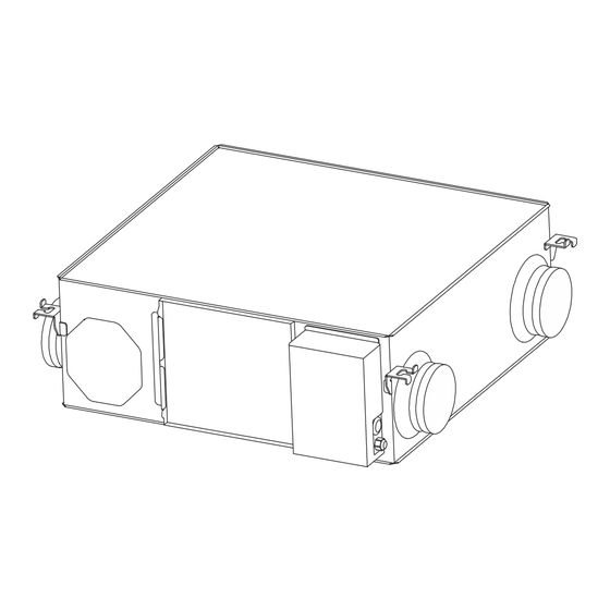
- Page 4 EN - UNIT DESCRIPTION Principle and function Energy Recovery ventilator is a kind of ventilator equipment for air energy recovery. It is composed of supply air fan, exhaust fan, total heat exchanger, primary filter of original air, primary filter of return air, etc. Energy Recovery ventilator function: the purified fresh air is constinuously transported to the room through the air supply outlet, and the indoor dirty air is discharged at the same time, so as to improve the indoor air quality.
- Page 5 EN - DIMENSIONS Dimensions Models CFA 350 to 1000 Nominal Diameter Model Diameter GVent 350 Gvent 650 GVent 800 Gvent 1000 Duct Connecting Ceiling Suspension Dimensions Duct Pitch Weight Fixture Pitch Flange Model (Kg) Gvent 350 GVent 650 946.5 1004...
- Page 6 Service ports should be installed to allow access for filter maintenance. 2 - Be sure the ceiling height is no less than Figure column in the table below. Inner Ceiling Model Height A Gvent 350 Gvent 650 GVent 800 Gvent1000...
- Page 7 EN - INSTALLATION CONSIDERATIONS 3 - Unit must not be installed close to boiler flues. 4 - Following phenomenon should be avoided in the ducting installation. Tight Curves Multiple Direction Changes Multiple Reducers / Crimped Duct 5 - Excessive use of flex-duct and long flex-duct runs should be avoided. 6 - Fire dampers must be fitted as per national and local fire regulations.
- Page 8 3 - The two outdoor vents should face downward toward the outside to prevent any rain water ingress. ( angle 1/100 1/50 ) 4 - Insulation must be with two ducts outside to prevent condensation. Material: Glass cotton, Thickness: 25mm. Standard Installation Examples GVent 350 to Gvent 1000...
- Page 9 Spec. of normal Model Spec. of power supply cable controller cable GVent 350 to Gvent 1000 3 x 1.5mm 4 x 0.5mm WARNING We do not accept any liability for any problems caused by the user’s self and non-authorized re-engineering to the electrical and control systems.
- Page 10 EN - PRECAUTIONS FOR USE AND COMMISSIONING Precautions for Use WARNING Loose or incorrect wiring connection can cause explosion or fire when the unit starts to work. Use only rated power voltage. Don’t install, move or re-install the unit by yourself. Improper action may cause unit instability, electric shock or fire.
- Page 11 EN - CONTROLLER INSTRUCTIONS Controller Instructions (HDK-CK22C) Name ON/OFF Button MODE Button UP Button DOWN Button SET Button Supply Air Fan ON/OFF Exhaust Air Fan ON/OFF Bypass Mode ON/OFF Heat Exchange Mode ON/OFF Pre Heating Heating Communication PM2.5 TOVC Clock Timed Power ON/OFF Time Time Period...
- Page 12 EN - CONTROLLER INSTRUCTIONS Operation Instructions 4 - Operation Mode: When it is turned on, the screen display is heat exchange mode, user can press the MODE button to switch the operating mode of the device. The sequence is heat exchange mode, bypass mode, automatic mode ( four periods mode ), and sleep mode, is switched cyclically.
- Page 13 EN - CONTROLLER INSTRUCTIONS Operation Instructions 4.4 - Sleep Mode In the sleep mode, the supply air fan and exhaust air fan are running in speed 1, and the screen becomes darker and standby after 30s. When the automatic bypass is not turned on (or the bypass mode opening conditions are not reached), the icon of the sleep mode and the heat exchange mode are long bright.
- Page 14 EN - CONTROLLER INSTRUCTIONS Operation Instructions 8 - Setting Positive and Negative Pressure User can set the speed of the supply air and exhaust air separately. If the positive pressure is needed, the speed of supply air should be higher than the speed of exhaust air; if the negative pressure is required, the speed of exhaust air should be higher than the speed of supply air;...
- Page 15 EN - CONTROLLER INSTRUCTIONS Operation Instructions 11 - Intelligent air volume compensation (PS: only applicable to the highest speed): During the long-term operation of the equipment, the filter screen will accumulate dust and gradually block, which will lead to the increase of equipment resistance and the decrease of air volume. In order to make up for the air volume loss, the air volume will be increased along with the regular pressurization of the supply and exhaust fans (the pressurization percentage can be set in the parameter item).
- Page 16 EN - CONTROLLER INSTRUCTIONS Operation Instructions 16 - One Button High Speed Application: In the kitchen or bathroom, the equipment can be turned on remotely through the rocker switch. One remote rocker switch control interface is reserved on the mainboard. When the interface is connected, the supply fan and exhaust fan operate under the highest speed.
- Page 17 EN - CONTROLLER INSTRUCTIONS Operation Instructions 21 - Temperature Adjustment Function Under the parameter item, press the " " and " " button to set the electric heating startup temperature, the range is 16-30. If the SA temperature is higher than the set temperature, both electric heating stops, and the preheating and heating displays are both extinguished.
- Page 18 EN - CONTROLLER INSTRUCTIONS Operation Instructions 25 - Parameter Table Setting Setting parameters: long press the "power button + up button" for more than 6 seconds under the power on state, and then short the "SET" button. Each time you press it, the parameter value will be increased by 1 until the parameter 19 is displayed circularly.
- Page 19 EN - MAINTENANCE Maintenance Before maintaining the system, cut off the power supply. Maintain the device after it WARNING stops completely to avoid damage. Energy Recovery Ventilation (purification) needs regular cleaning and maintenance. If it is not cleaned and maintained correctly and regularly, its filtration efficiency and heat exchanger efficiency will be greatly reduced.
- Page 20 EN - VALUE TABLE...
- Page 21 EN - CENTRALIZED CONTROL MODBUS-RTU Parameters: baud rate:9600, no check,1 digit stop position, 8 bit data. Support Function code: Read 03, write 06 Communication data interval >=200ms...
- Page 22 EN - CENTRALIZED CONTROL MODBUS-RTU...
- Page 23 EN - CONTACTS www.globovac.com Email: globovac@globovac.com Tel Export: +44 (0) 1823 665 777 Tel UK: +44 (0) 1293 772 165 Mobile: +44 (0) 1293 665 175 Office: Globovac Ltd, 8C Castle Road, Chelston Business Park, Wellington, Somerset, TA21 9JQ, UNITED KINGDOM...
Need help?
Do you have a question about the GVent 350 and is the answer not in the manual?
Questions and answers