Advertisement
Quick Links
Advertisement

Related Manuals for OPTOKON PM-215E


Summary of Contents for OPTOKON PM-215E
- Page 1 PM-215E Pocket Optical Power Meter User Manual Version: Date: 25.10.2024...
- Page 2 PM-125E User Manual Table of contents General Provisions .................... 3 Introduction ...................... 5 Features ......................5 Application ....................... 5 Accessories ...................... 6 5.1. Standard ....................6 5.2. Optional ....................6 Specifications ....................7 Safety information ..................... 7 Maintenance ..................... 8 8.1.
- Page 3 11. Remote control and data transfer ..............19 11.1. Terminal application ................19 11.2. PM-215E control application ..............19 12. dB to %, dBm, mW conversion table ..............22 13. Calibration and service center ................22 14. Contact ......................23...
- Page 4 OPTOKON, a.s. is not responsible for the loss or damage of the product due to natural disasters or other effects of natural conditions. OPTOKON, a.s.
- Page 5 PM-125E User Manual The information and descriptions provided in this document are the property of OPTOKON, a.s. Such information and descriptions may not be copied or reproduced in any way, nor disseminated or distributed, without the express prior written consent of the Company.
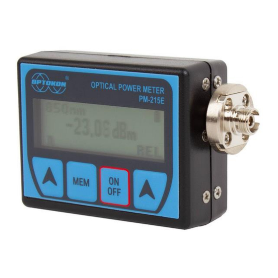
- Page 6 PM-125E User Manual 2. Introduction The PM-215E Optical Power Meter is a small, pocket-size low-cost item. The small size does not prevent the optical meter fulfilling all the technical requirements for field equipment. The unit can be easily carried in the pocket or on a belt. It can be placed within rack mount ODF’s with the display on the top or on the side.
- Page 7 PM-125E User Manual 5. Accessories 5.1. Standard • Universal 2.5 mm adapter (TE-ADP-250) • Universal SFF 1.25 mm adapter (TE-ADP-125) • FC (TF-ADP-FC), LC (TF-ADP-LC), SC (TF-ADP-SC) adapters • Power charging adapter • Traceable calibration certificate • Hard carrying case (TE-HC-01) •...
- Page 8 Battery working time > 75hrs Between charges 7. Safety information The PM-215E power meter emits no optical power itself and does not pose any hazard to the user. WARNING • Never use magnifying devices to inspect optical fiber ends unless you are certain that no optical power is being emitted.
- Page 9 Avoid fully charging the battery pack before storing the PM-215E; an optimal storage charge level is around 70%. • If you do not plan to use the PM-215E for an extended period, charge the battery pack once every six months. •...
- Page 10 PM-125E User Manual 8.3. Optical connector maintenance • Cleanliness directly impacts the performance of optical fiber systems. • Ensure all connectors and fiber end faces are clean before testing. • Clean all connectors, adapters, and attenuators thoroughly before making any connections.
- Page 11 PM-125E User Manual 9.2. Automatic shutdown The automatic shutdown feature (Auto OFF) turns the device off after 5 minutes of inactivity. To enable this feature, press the “ON/OFF” button, and at the shutdown screen, press the right arrow button to enable or disable the Auto OFF feature. If Auto OFF is enabled, the unit will display an hourglass ( ) symbol next to the battery charge indicator.
- Page 12 PM-125E User Manual 9.4. Menu #2 – Relative power measurement mode When the relative power measurement mode is active, the display shows the optical insertion loss value in dB units, based on the previously set reference. Press the “ABS” button to return the unit to menu #1 – absolute power measurement mode.
- Page 13 9.5. Working with internal memory The PM-215E memory has a structured, two-level organization. The results are stored in memory positions (MEM) in folders called Cable (CAB). A maximum of 100 results can be stored in the internal memory. This number is shared...
- Page 14 Use the “+” and “-” buttons to select the memory position you want to view. The stored value at each memory position will be displayed as you browse through them. Press “OK” to exit the memory browser. 9.5.3. Upload data Connect the PM-215E unit to a computer using the included USB cable.
- Page 15 By default, the device is configured to display 850, 1300, 1310, 1490, 1550, and 1625 nm wavelengths. The wavelengths accessible in the interface can be changed from a list of supported wavelengths. You can do this using the PM-215E application or directly on the device.
- Page 16 PM-125E User Manual To change the wavelengths on the device itself follow these steps: Press “ON/OFF”, you can access additional settings from the shutdown screen: λ – change accessible wavelengths - automatic shutoff settings Press “λ” to display the wavelength settings Use the left and right arrows to switch between wavelengths ON/OFF next to the wavelength indicates if it is displayed in the interface or not...
- Page 17 This test measures the power difference between the input and output of the link. The PM-215E optical power meter and LS-215E light source are used for this test, with the LS-215E as the transmitter and the PM-215E as the receiver.
- Page 18 In Method C3, two master patch cords are used to set the reference. This method cancels the effects of the master patch cords and one adapter for all subsequent measurements. 10.3.1. Setting the reference 1. Connect the first master patch cord to the power meter (PM-215E).
- Page 19 PM-125E User Manual 2. Connect the second master patch cord to the light source (LS-215E). 3. Use the master adapter to connect the two fiber ends. 4. Power on the light source and select the appropriate wavelength by pressing "λ." 5.
- Page 20 PM-125E User Manual 11. Remote control and data transfer You can control the PM-215E power meter from a connected PC using these methods: 1. Using a terminal application (Hyper Terminal, Putty, Tera Term, etc.) 2. Using the OPTOKON provided PM-215E control application 11.1.
- Page 21 PM-125E User Manual 3. Select the COM port the device is connected to, the application will connect, display the device model and serial number and start mirroring the device display in the application window 4. From the main view you can cycle through the wavelengths, switch between relative and absolute mode, and set a reference measurement 5.
- Page 22 9. Using the “Firmware Upgrade” box you can upload a new firmware to the device, this is limited only to official firmware released by OPTOKON 10. Using the “Select Wavelengths” box you can toggle which wavelengths from the list of supported are displayed in the power meter interface, confirm by pressing the “Save”...
- Page 23 74,9 1,26 80,0 2,00 84,2 3,16 87,7 5,01 90,0 10,00 93,7 15,84 96,8 31,62 99,0 50,12 99,9 100,00 13. Calibration and service center OPTOKON, a.s. Červený Kříž 250 586 01 Jihlava Czech Republic Tel.: +420 564 040 111 kalibrace@optokon.com www.optokon.com...
- Page 24 Tel.: +420 564 040 111 info@optokon.com www.optokon.com is a registered trademark of OPTOKON, a.s. Other names and trademarks mentioned herein may be the trademarks of their respective owners. All rights reserved. No part of the document may be reproduced under any conditions or in any form –...
Need help?
Do you have a question about the PM-215E and is the answer not in the manual?
Questions and answers