Table of Contents
Advertisement
Quick Links
PM-800-GL
Optical Power Meter
INSTRUCTION MANUAL
is registered trademark of OPTOKON, a.s. Other names and trademarks mentioned herein may be the
trademarks of their respective owners.
OPTOKON, a.s., Cerveny Kriz 250, 586 01 Jihlava, Czech Republic
tel. +420 564 040 111, fax +420 564 040 134, WWW.OPTOKON.COM, INFO@OPTOKON.CZ
s/w: 1.2
23/05/2017
Advertisement
Table of Contents

Related Manuals for OPTOKON PM-800-GL


Summary of Contents for OPTOKON PM-800-GL
- Page 1 PM-800-GL Optical Power Meter INSTRUCTION MANUAL is registered trademark of OPTOKON, a.s. Other names and trademarks mentioned herein may be the trademarks of their respective owners. OPTOKON, a.s., Cerveny Kriz 250, 586 01 Jihlava, Czech Republic tel. +420 564 040 111, fax +420 564 040 134, WWW.OPTOKON.COM, INFO@OPTOKON.CZ s/w: 1.2...
- Page 2 OPTOKON, a.s. Other names and trademarks mentioned herein may be the trademarks of their respective owners All rights reserved. No parts of this work may be reproduced in any form or by any means - graphic, electronic, or mechanical, including photocopying, recording, taping or information storage and retrieval systems - without the written permission of the publisher.
-
Page 3: Table Of Contents
PM-800-GL INSTRUCTION MANUAL Contents Introduction ....................4 Features ...................... 4 Application ....................4 Accessories ....................5 Standard ........................5 Optional ........................5 Specifications ....................6 Safety information ..................7 Maintenance ....................10 Battery care ......................10 Instrument care ......................10 Recommended cleaning and mating instructions ............. -
Page 4: Introduction
5 years. Batteries can be charged via a USB port or external AC/DC adaptor. The microprocessor controlled charging process ensures optimal battery status and extended operation time. The PM-800-GL series can measure a wide range of optical power level, -70 to +36 dBm. 2 Features ... -
Page 5: Accessories
PM-800-GL INSTRUCTION MANUAL 4 Accessories 4.1 Standard 4.2 Optional Power meter Master patchcords Changeable input adaptors Master adaptors USB cable Li-Pol battery Power charging adapter 5 V DC Calibration certificate Hard carrying case TE-HC-03 ... -
Page 6: Specifications
PM-800-GL INSTRUCTION MANUAL 5 Specifications General specifications Value Unit Note Dimensions 165 x 80 x 40 with TE‐AGP‐250 adapter Weight with battery Discharging / charging Operation temperature ‐10 to + 60 / 0 to +45 °C battery Storage temperature ‐10 to + 45 °C Humidity (non‐ 0 to 95 % condensing) PM‐800‐ PM‐800‐ PM‐800‐ PM‐800‐ Power Meter 06 ... -
Page 7: Safety Information
PM-800-GL INSTRUCTION MANUAL 7 Safety information The PM-800 instrument emits no optical power itself and does not create any hazards to the user. To ensure a high level of operator safety during installation, commissioning and operating the equipment, as well as ensuring that the equipment remains undamaged, it is necessary to consider the following general warnings and recommendations. - Page 8 PM-800-GL INSTRUCTION MANUAL classification system. The revised system is part of the revised IEC 60825 standard. From 2007, the revised system is also incorporated into the US-oriented ANSI Laser Safety Standard (ANSI Z136.1). Since 2007, labeling according to the revised system is accepted by the FDA on laser products imported into the US.
- Page 9 PM-800-GL INSTRUCTION MANUAL Class 2M A Class 2M laser is safe because of the blink reflex if not viewed through optical instruments. As with class 1M, this applies to laser beams with a large diameter or large divergence, for which the amount of light passing through the pupil cannot exceed the limits for class 2.
-
Page 10: Maintenance
PM-800-GL INSTRUCTION MANUAL 8 Maintenance 8.1 Battery care The PM-800 comes equipped with a built-in charger and is powered by Li-Pol battery. Charging – via USB port (PC) or by using external USB power charging adaptor (standard accessories) Before using the PM-800 for first time, charge fully the battery. -
Page 11: Recommended Cleaning And Mating Instructions
PM-800-GL INSTRUCTION MANUAL 8.3 Recommended cleaning and mating instructions Cleanliness will affect the performance of an residual alcohol. For oversized adapters optical fiber system. Perform the following (biconic), slightly blow the middle of the pipe procedures prior the installation. Clean all cleaner fog better surface contact. -
Page 12: Instrument And Button Function Description
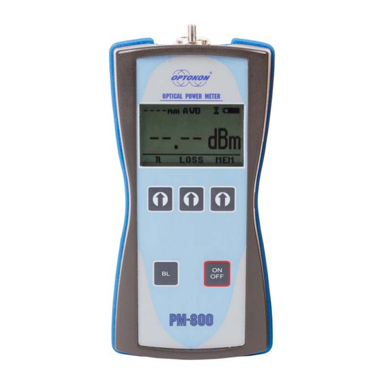
PM-800-GL INSTRUCTION MANUAL 9 Instrument and button function description Power meter port with 2.5 mm universal adaptor Calibration label LCD display USB port (charging) Operating keys BL key ON/OFF key [ON/OFF] Press to turn the unit on. Press to turn the unit off. -
Page 13: Menu #1 - Absolute Power Measurement Mode
PM-800-GL INSTRUCTION MANUAL 9.1 Menu #1 – Absolute power measurement mode In the absolute power measurement mode the absolute value of the optical signal in dBm units is shown on the display. This screen will appear after the instrument is switched on and information regarding the type of device, serial number and firmware version will appear. -
Page 14: Menu #2 - Relative Power Measurement Mode
PM-800-GL INSTRUCTION MANUAL 9.2 Menu #2 – Relative power measurement mode In the relative power measurement mode is on the value of optical insertion loss in dB units which corresponds to performed reference is shown on the display. Reading the display:... -
Page 15: Menu #3 - Working With The Internal Memory
PM-800-GL INSTRUCTION MANUAL 9.3 Menu #3 – Working with the internal memory The memory of PM-800 has a structured, two-level organization. The results are stored in memory positions (FIBER) in folders called Cable (CABLE). See table below: CABLE001 FIBER001 FIBER002... -
Page 16: Save Result
PM-800-GL INSTRUCTION MANUAL 9.3.1 SAVE RESULT 1. By using [UP] [DOWN] select “SAVE RESULT” and press [OK]. CABLE 001 FIBER 004 STORED : 003 - CABLE + FIBER 2. Select the cable (folder) using [- CABLE +], the unit will display the number of saved results under the selected cable, then press [FIBER]. -
Page 17: Browse Results
PM-800-GL INSTRUCTION MANUAL 9.3.2 BROWSE RESULTS 1. By using [UP] [DOWN] select “BROWSE RESULTS” and press [OK] CABLE 001 STORED : 003 - CABLE + FIBER 2. Select the cable (folder) using [- CABLE +], the unit will display the number of saved results under the selected cable, then press [FIBER]. -
Page 18: Erase Memory
PM-800-GL INSTRUCTION MANUAL 9.3.4 ERASE MEMORY 1. By using [UP] [DOWN] select “ERASE MEMORY” and press [OK]. ERASE MEMORY ERASE MEMORY CONFIRM CONFIRM 2. Press [CONFIRM] to erase memory or [NO] for return to main screen. 9.3.5 HOME 1. By using [UP] [DOWN] select “HOME”. -
Page 19: Measurement Loss
PM-800-GL INSTRUCTION MANUAL 10 Measurement loss 10.1 Basic theory Loss measures the signal degradation in a fiber optic cable. A light source injects an optical signal of the appropriate wavelength into the fiber and a power meter measures the received signal at the same wavelength. -
Page 20: Method 6
PM-800-GL INSTRUCTION MANUAL 10.2 Method 6 For method 6 two master cords are used to set the reference. Method 6 cancels the effects of the master cords and one adaptor for all subsequent measurements. 10.2.1 Setting the reference 1. Connect the first master cord to the power meter (PM-800). -
Page 21: Measurement Loss
PM-800-GL INSTRUCTION MANUAL 10.2.2 Measurement Loss 1. Do not disconnect the master cords from the light source and power meter. 2. Disconnect second master cord from the adaptor. 3. Connect the trace to be measured between the master cords. An extra master adaptor is required (pic.2). -
Page 22: Method 7
PM-800-GL INSTRUCTION MANUAL 10.3 Method 7 For method 7, one master cord is used to set the reference. The master cord will be cancelled for all subsequent measurements. 10.3.1 Setting the reference 1. Connect the master cord to the power meter (PM-800). -
Page 23: Measurement Loss
PM-800-GL INSTRUCTION MANUAL 10.3.2 Measurement Loss 1. Do not disconnect the master cord from the light source. 2. Disconnect the master cord from the power meter port. 3. Connect the trace to be measured between the power meter port and the master cord that is attached to the light source. -
Page 24: High Power Measurement
PM-800-GL INSTRUCTION MANUAL 10.4 High power measurement There are 4 levels of dynamic range, up to +36 dBm depending on photodetector type. Use the right type of PM-800 in accordance of expecting max power level in your network. PM-800-06: -70 to +6 dBm... -
Page 25: Setting Up Data Transfer
1. Connect the PM-800 to a PC using the USB cable provided and turn the PM-800 on. The PC will prompt you to install the drivers for new hardware. Use the drivers provided by OPTOKON. These drivers will create a virtual serial com port. 2. Start the Hyper Terminal Start >>... - Page 26 PM-800-GL INSTRUCTION MANUAL 4. Choose the virtual serial port the PM-800 is connected to, then click on OK 5. Set “Bits per second” to 19200, then click on OK...
- Page 27 PM-800-GL INSTRUCTION MANUAL 6. Go to the menu in PM-800 and push [MEM], select [UPLOAD MEMORY], [OK]. The stored data will be transferred to the PC in this format: stored values fiber wavelength position cable folder The data from this window can be easily copied to any other application.
-
Page 28: Power Loss And Decibels
PM-800-GL INSTRUCTION MANUAL 12 Power loss and decibels Loss (dB) % Loss Power (mW) 0.00001 0.0001 0.001 0.01 0.10 10.9 0.13 12.9 0.16 14.9 0.20 16.8 0.25 18.7 0.32 20.6 0.40 36.9 0.50 49.9 0.63 60.2 0.79 68.4 1.00 74.9 1.26... -
Page 29: Notes
PM-800-GL INSTRUCTION MANUAL 13 Notes ................................................................................................................................................................................................................................................................................................................................................................................................................ -
Page 30: Calibration, Service Center
14 Calibration, service center OPTOKON, a.s. Červený Kříž 250 586 01 Jihlava Czech Republic tel.: +420 564 040 111 fax: +420 564 040 134 OPTOKON@OPTOKON.CZ WWW.OPTOKON.COM...
Need help?
Do you have a question about the PM-800-GL and is the answer not in the manual?
Questions and answers