Table of Contents
Advertisement
Quick Links
PM-240-MTP
Multifiber Optical Power
Meter
INSTRUCTION MANUAL
Revision:1.0
is registered trademark of OPTOKON, a.s. Other names and trademarks mentioned herein may be the
trademarks of their respective owners.
OPTOKON, a.s., Cerveny Kriz 250, 586 01 Jihlava, Czech Republic
tel. +420 564 040 111, fax +420 564 040 134, WWW.OPTOKON.COM, INFO@OPTOKON.CZ
s/w: 1.2
19/01/2017
Advertisement
Table of Contents

Related Manuals for OPTOKON PM-240-MTP


Summary of Contents for OPTOKON PM-240-MTP
- Page 1 Meter INSTRUCTION MANUAL Revision:1.0 is registered trademark of OPTOKON, a.s. Other names and trademarks mentioned herein may be the trademarks of their respective owners. OPTOKON, a.s., Cerveny Kriz 250, 586 01 Jihlava, Czech Republic tel. +420 564 040 111, fax +420 564 040 134, WWW.OPTOKON.COM, INFO@OPTOKON.CZ s/w: 1.2...
- Page 2 OPTOKON, a.s. Other names and trademarks mentioned herein may be the trademarks of their respective owners. OPTOKON, a.s., Cerveny Kriz 250, 586 01 Jihlava, Czech Republic tel. +420 564 040 111, fax +420 564 040 134, WWW.OPTOKON.COM, INFO@OPTOKON.CZ s/w: 1.2...
- Page 3 OPTOKON, a.s. Other names and trademarks mentioned herein may be the trademarks of their respective owners All rights reserved. No parts of this work may be reproduced in any form or by any means - graphic, electronic, or mechanical, including photocopying, recording, taping or information storage and retrieval systems - without the written permission of the publisher.
-
Page 4: Table Of Contents
PM-240-MTP INSTRUCTION MANUAL Contents Introduction ....................4 Features ...................... 4 Application ....................4 Accessories ....................5 Standard ........................5 Optional ........................5 Specifications ....................5 Safety information ..................6 Maintenance ....................7 Battery care ........................ 7 Instrument care ......................7 Recommended cleaning and mating instructions Chyba! Záložka není... -
Page 5: Introduction
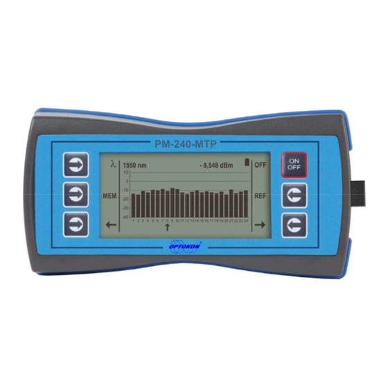
PM-240-MTP INSTRUCTION MANUAL 1 Introduction The PM-240-MTP optical power meter is designed to measure absolute or relative optical power in optical networks terminated with 12 – 24 multifiber MTP/MPO connectors. The tester can measure simultanously optical power level in all up to 24 fibers of MTP/MPO connectors, it can recognize “live”... -
Page 6: Accessories
PM-240-MTP INSTRUCTION MANUAL 4 Accessories 4.1 Standard Hard carrying case SmartProtocol PC software Data Exporter PC software Power charging adaptor Traceable calibration certificate USB connection cable 5 Optional Master MTP/MPO connector patchcord 6 Specifications... -
Page 7: Safety Information
PM-240-MTP INSTRUCTION MANUAL 7 Safety information The PM-240-MTPP instrument emits no optical power itself and does not create any hazards to the user. To ensure a high level of operator safety during installation, commissioning and operating the equipment, as well as ensuring that the equipment remains undamaged, it is necessary to consider the following general warnings and recommendations. -
Page 8: Maintenance
PM-240-MTP INSTRUCTION MANUAL 8 Maintenance 8.1 Battery care The PM-240-MTP comes equipped with a built-in charger and is powered by Li-Pol rechargeable batteries (standard accessories). Charging – via USB port (PC) or by an external USB power charging adaptor (standard accessories) ... -
Page 9: Instrument And Button Function Description
PM-240-MTP INSTRUCTION MANUAL 9 Instrument and button function description LCD display Battery status MTP/MPO adapter ON/OFF USB adapter Operation buttons [ON/OFF] Press to turn the unit on. Hold ON/OFF (about 4 sec) to turn the unit on in backlight mode. -
Page 10: Menu #1 - Absolute Power Measurement Mode
PM-240-MTP INSTRUCTION MANUAL 9.1 Absolute power measurement mode In the absolute power measurement mode the absolute value of the optical signal in dBm units is shown on the display. This screen will appear after the instrument is switched on and information regarding the type of device, serial number and firmware version will appear. -
Page 11: Menu #2 - Relative Power Measurement Mode
PM-240-MTP INSTRUCTION MANUAL 9.2 Menu #1 – Relative power measurement mode In the relative power measurement mode is on the value of optical insertion loss in dB units which corresponds to performed reference is shown on the display. Reading the display:... - Page 12 PM-240-MTP INSTRUCTION MANUAL CABLE001 FIBER001 FIBER002 FIBER003 FIBER004 FIBER005 FIBER006 ....FIBERXXX CABLE002 FIBER001 FIBER002 FIBER003 FIBER004 FIBER005 FIBER006 ....FIBERXXX ....CABLEXXX FIBER001 FIBER002 FIBER003 FIBER004 FIBER005 FIBER006 ....FIBERXXX This screen will appear after pressing [MEM] key from Menu#1 or Menu#2...
-
Page 13: Save Result
PM-240-MTP INSTRUCTION MANUAL 9.3.1 SAVE RESULT 1. By using [UP] [DOWN] select “SAVE RESULT” and press [OK]. CABLE 001 FIBER 004 STORED : 003 - CABLE + FIBER 2. Select the cable (folder) using [- CABLE +], the unit will display the number of saved results under the selected cable, then press [FIBER]. -
Page 14: Browse Results
PM-240-MTP INSTRUCTION MANUAL 9.3.2 BROWSE RESULTS 1. By using [UP] [DOWN] select “BROWSE RESULTS” and press [OK] CABLE 001 STORED : 003 - CABLE + FIBER 2. Select the cable (folder) using [- CABLE +], the unit will display the number of saved results under the selected cable, then press [FIBER]. -
Page 15: Erase Memory
PM-240-MTP INSTRUCTION MANUAL 9.3.4 ERASE MEMORY 1. By using [UP] [DOWN] select “ERASE MEMORY” and press [OK]. ERASE MEMORY ERASE MEMORY CONFIRM CONFIRM 2. Press [CONFIRM] to erase memory or [NO] for return to main screen. 9.3.5 HOME 1. By using [UP] [DOWN] select “HOME”. -
Page 16: Measurement Loss
PM-240-MTP INSTRUCTION MANUAL 10 Measurement loss 10.1 Basic theory Loss measures the signal degradation in a fiber optic cable. A light source injects an optical signal of the appropriate wavelength into the fiber and a power meter measures the received signal at the same wavelength. -
Page 17: Method 6
PM-240-MTP INSTRUCTION MANUAL 10.2 Method 6 For method 6 two master cords are used to set the reference. Method 6 cancels the effects of the master cords and one adaptor for all subsequent measurements. 10.2.1 Setting the reference 1. Connect the first master cord to the power meter (PM-800). -
Page 18: Measurement Loss
PM-240-MTP INSTRUCTION MANUAL 10.2.2 Measurement Loss 1. Do not disconnect the master cords from the light source and power meter. 2. Disconnect second master cord from the adaptor. 3. Connect the trace to be measured between the master cords. An extra master adaptor is required (pic.2). -
Page 19: Method 7
PM-240-MTP INSTRUCTION MANUAL 10.3 Method 7 For method 7, one master cord is used to set the reference. The master cord will be cancelled for all subsequent measurements. 10.3.1 Setting the reference 1. Connect the master cord to the power meter (PM-800). -
Page 20: Measurement Loss
PM-240-MTP INSTRUCTION MANUAL 10.3.2 Measurement Loss 1. Do not disconnect the master cord from the light source. 2. Disconnect the master cord from the power meter port. 3. Connect the trace to be measured between the power meter port and the master cord that is attached to the light source. -
Page 21: High Power Measurement
PM-240-MTP INSTRUCTION MANUAL 10.4 High power measurement For measurement up to +13 dBm is intended PM-800: -70 dBm to +13 dBm for 1300, 1310, 1490, 1550, 1625 nm (standard measurement methods 6 or 7 described above) For high power measurement is intended PM-800H:... -
Page 22: Setting Up Data Transfer
1. Connect the PM-800 to a PC using the USB cable provided and turn the PM-800 on. The PC will prompt you to install the drivers for new hardware. Use the drivers provided by OPTOKON. These drivers will create a virtual serial com port. 2. Start the Hyper Terminal Start >>... - Page 23 PM-240-MTP INSTRUCTION MANUAL 4. Choose the virtual serial port the PM-800 is connected to, then click on OK 5. Set “Bits per second” to 19200, then click on OK...
- Page 24 PM-240-MTP INSTRUCTION MANUAL 6. Go to the menu in PM-800 and push [MEM], select [UPLOAD MEMORY], [OK]. The stored data will be transferred to the PC in this format: stored values fiber wavelength position cable folder The data from this window can be easily copied to any other application.
-
Page 25: Power Loss And Decibels
PM-240-MTP INSTRUCTION MANUAL 12 Power loss and decibels Loss (dB) % Loss Power (mW) 0.00001 0.0001 0.001 0.01 0.10 10.9 0.13 12.9 0.16 14.9 0.20 16.8 0.25 18.7 0.32 20.6 0.40 36.9 0.50 49.9 0.63 60.2 0.79 68.4 1.00 74.9 1.26... -
Page 26: Notes
PM-240-MTP INSTRUCTION MANUAL 13 Notes ................................................................................................................................................................................................................................................................................................................................................................................................................ -
Page 27: Calibration, Service Center
14 Calibration, service center OPTOKON, a.s. Červený Kříž 250 586 01 Jihlava Czech Republic tel.: +420 564 040 111 fax: +420 564 040 134 OPTOKON@OPTOKON.CZ WWW.OPTOKON.COM...
Need help?
Do you have a question about the PM-240-MTP and is the answer not in the manual?
Questions and answers