Advertisement
Quick Links
Safe Operation Practices • Set-Up • Operation • Maintenance • Service • Troubleshooting • Warranty
'
operator
s manual
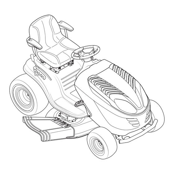
Auto Drive Lawn Tractor
WARNING
READ AND FOLLOW ALL SAFETY RULES AND INSTRUCTIONS IN THIS MANUAL
BEFORE ATTEMPTING TO OPERATE THIS MACHINE.
FAILURE TO COMPLY WITH THESE INSTRUCTIONS MAY RESULT IN PERSONAL INJURY.
P. O. Box 1386, 97 Kent Avenue, KITCHENER, ONTARIO, CANADA N2G 4J1
Printed In USA
769-09635A
5.8.15
Advertisement

Subscribe to Our Youtube Channel
Related Manuals for MTD YARD-MAN 13AV78YS501


Summary of Contents for MTD YARD-MAN 13AV78YS501
- Page 1 Safe Operation Practices • Set-Up • Operation • Maintenance • Service • Troubleshooting • Warranty ’ operator s manual Auto Drive Lawn Tractor WARNING READ AND FOLLOW ALL SAFETY RULES AND INSTRUCTIONS IN THIS MANUAL BEFORE ATTEMPTING TO OPERATE THIS MACHINE. FAILURE TO COMPLY WITH THESE INSTRUCTIONS MAY RESULT IN PERSONAL INJURY.
- Page 2 Choose from the options below: ◊ Visit our web at www.yardman.ca ◊ Locate your nearest dealer from Customer Support: 1-800-668-1238 ◊ Contact MTD CANADA • P.O. Box 1386 • 97 Kent Avenue • Kitchener, Ontario, Canada • N2G 4J1...
- Page 3 Important Safe Operation Practices WARNING: This symbol points out important safety instructions which, if not followed, could endanger the personal safety and/or property of yourself and others. Read and follow all instructions in this manual before attempting to operate this machine. Failure to comply with these instructions may result in personal injury.
- Page 4 Mow only in daylight or good artificial light. Never carry passengers. Mow up and down slopes, not across. Exercise extreme caution when changing direction on slopes. Disengage blade(s) before shifting into reverse. Back up slowly. Always look down and behind before and while Watch for holes, ruts, bumps, rocks, or other hidden backing to avoid a back-over accident.
- Page 5 Be alert and turn machine off if a child enters the When practical, remove gas-powered equipment area. from the truck or trailer and refuel it on the ground. If this is not possible, then refuel such equipment on Before and while backing, look behind and down for a trailer with a portable container, rather than from a small children.
- Page 6 Do not modify engine Mower blades are sharp. Wrap the blade or wear gloves, and use extra caution when servicing them. To avoid serious injury or death, do not modify engine in any Keep all nuts, bolts, and screws tight to be sure the way.
- Page 7 Safety Symbols This page depicts and describes safety symbols that may appear on this product. Read, understand, and follow all instructions on the machine before attempting to assemble and operate. Symbol Description READ THE OPERATOR’S MANUAL(S) Read, understand, and follow all instructions in the manual(s) before attempting to assemble and operate DANGER—...
- Page 8 2 — i ection mportant peration racticeS...
- Page 9 Assembly & Set-Up Assembly & Set-Up Tractor Set-Up NOTE: If the battery is put into service after the date shown on top/side of battery, charge the battery as instructed in the NOTE: This Operators Manual covers a range of product Maintenance section your Operator’s Manual prior to operating specifications for various models.
- Page 10 Attaching The Steering Wheel Attaching The Seat If the steering wheel for your tractor did not come attached, the NOTE: For shipping reasons, the seat is either fastened to hardware for attaching it has been packed within the steering the tractor seat’s pivot bracket with a plastic tie, or mounted wheel, beneath the steering wheel cap.
- Page 11 Figure 3-6 Tire Pressure WARNING! Maximum tire pressure under any Figure 3-7 circumstances is 30 psi. Equal tire pressure should be maintained at all times. Never exceed the maximum inflation pressure shown on the sidewall of the tire. The recommended operating tire pressure is: •...
- Page 12 Controls and Features Throttle/Choke Lever Parking Brake Lever Ignition Switch Module Brake Pedal Auto Drive Pedal Service Minder and Hour Meter Shift Lever Deck Lift Lever PTO (Blade Engage) Lever Figure 4-1 Lawn Tractor controls and features are illustrated in Fig 4-1 and described on the following pages. WARNING! Read and follow all safety rules and instructions in this manual, including the entire Operation section, before attempting to operate this machine.
- Page 13 Throttle Control Lever CHOKE The throttle control lever is located on the left side FAST of the tractor’s dash panel. This lever controls the speed of the engine and when pushed all the way forward, the choke control also. When set in a given position, the throttle will maintain a SLOW...
- Page 14 Ignition Switch Module LCD Service Minder & Hour Meter When the ignition key is rotated WARNING! Never out of the STOP position but leave a running not into the START position, the machine LCD Service Minder and Hour unattended. Always Meter will briefly disply the disengage PTO, set battery voltage, followed by the...
- Page 15 Reverse protection of the operator. If the interlock system should ever Caution malfunction, do not operate the tractor. Contact an authorized Mode Normal MTD service dealer. Position Driving • The safety interlock system prevents the engine from cranking Mode or starting unless the parking brake is engaged, and the PTO (Blade Engage) lever is in the disengaged (OFF) position.
- Page 16 Starting the Engine Once activated (indicator light ON), the tractor can be driven in reverse with the cutting blades (PTO) engaged. WARNING! Do not operate the tractor if the Always look down and behind before and while backing to interlock system is malfunctioning. This system was make sure no children are around.
- Page 17 Driving The Tractor Engaging the Blades WARNING! Engaging the PTO (Blade Engage) transfers power to the cutting Avoid sudden starts, excessive speed deck or other (separately available) attachments. To engage the and sudden stops. blades, proceed as follows: WARNING! Do not leave the seat of the tractor Move the throttle control lever to the FAST (rabbit) position.
- Page 18 Mowing NOTE: It is not necessary to remove the discharge chute to operate the mower with the mulch kit installed. WARNING! To help avoid blade contact or a WARNING! Never operate the mower without the thrown object injury, keep bystanders, helpers, discharge chute properly attached.
- Page 19 Maintenance & Adjustments Maintenance Spark Plug The spark plug should be cleaned and the gap reset once a WARNING! Before performing any maintenance or season. Spark plug replacement is recommended at the start repairs, disengage PTO, move shift lever into neutral of each mowing season.
- Page 20 Battery Failures Deck Wash System™ Some common causes for battery failure are: If your tractor’s deck is equipped with a water port on its surface as part of its Deck Wash System™, follow these instructions to • Incorrect initial activation utilize this feature.
- Page 21 IMPORTANT: Side to Side After cleaning your deck with the Deck Wash System™ , return to the operator’s position and engage the PTO. If the cutting deck appears to be mowing unevenly, a side to side Keep the cutting deck running for a minimum of two minutes, adjustment can be performed.
- Page 22 NOTE: This Operators Manual covers a range of product specifications for various models. Characteristics and features discussed and/ or illustrated in this manual may not be applicable to all models. MTD LLC reserves the right to change product specifications, designs and equipment without notice and without incurring obligation.
- Page 23 Service Cutting Deck Removal On 38” Decks: Looking at the cutting deck from the left side of the tractor, locate the bow tie pin that secures the NOTE: Models equipped with a 38-inch deck have one deck idler deck support rod on the rear left side of the deck. See Fig. pulley.
- Page 24 Tires On all decks: Move the deck lift lever into the top notch on the right fender to raise the deck lift arms up and out of WARNING! the way. Never exceed the maximum inflation pressure shown on the sidewall of tire. On 38”...
- Page 25 Charging WARNING! Batteries give off an explosive gas while charging. Charge the battery in a well ventilated area and keep away from an open flame or pilot light as on a water heater, space heater, furnace, clothes dryer or other gas appliances. CAUTION: When charging your tractor’s battery, use only a charger designed for 12V lead-acid...
- Page 26 (i.e. air/impact wrench) in order to change the tractor’s drive belt. removing the belt. See an authorized MTD Service Dealer to have your drive belt Remove the deck belt from around all pulleys, including replaced or phone Customer Support as instructed on page 2 for the deck idler pulley.
- Page 27 38-Inch Deck Engine Pulley Idler Bracket Deck Idler Pulley Figure 7-10 42 & 46-Inch Deck Figure 7-11 7 — S ection ervice...
- Page 28 Troubleshooting Problem Cause Remedy Engine fails to start 1. PTO/Blade engaged. 1. Place knob (or lever) in disengaged (OFF) position. 2. Spark plug wire disconnected. 2. Connect wire to spark plug. 3. Fuel tank empty, or stale fuel. 3. Fill tank with clean, fresh (less than 30 days old) gas.
- Page 29 Attachments & Accessories The following attachments and accessories are compatible with your lawn tractor. See your authorized dealer or the retailer from which you purchased your tractor for information regarding price and availability. CAUTION: Your lawn tractor is NOT designed for use with any type of ground-engaging attachments (e.g. tiller or moldboard plow).
- Page 30 Replacement Parts Component Part Number and Description 954-04060C Drive Belt (Mowing Deck) 42” Deck 954-04219 Drive Belt (Mowing Deck) 46” Deck 918-06991 Deck Spindle 42” Deck 918-06989 Deck Spindle 46” Deck 942-04308 Blade (42” Deck) 942-04290 Blade (46” Deck) 925-1707D Battery 951-12179B Fuel Tank Cap...
- Page 31 How to Obtain Service: Warranty service is available, with proof of purchase, through your local MTD Autho- rized Service Dealer. If you do not know the dealer in your area, please write to the Service Department of MTD PRODUCTS LIMITED, P.O. BOX 1386, KITCHENER, ONTARIO N2G 4J1. The return of a complete unit will not be accepted by the factory unless prior written permission has been extended by MTD PRODUCTS LIMITED.
- Page 32 Any warranted part that is not scheduled for replacement as required maintenance in the written instructions supplied is warranted for the warranty period stated above. If the part fails during the period of warranty coverage, the part will be repaired or replaced by MTD Consumer Group Inc according to subsection (4) below.
- Page 33 NOTE: If you require warranty service in Canada and your product was sold by MTD Products Limited within Canada to the retailer you purchased it from in Canada then the MTD Consumer Group Inc portion of this warranty will be honored by MTD Products Limited in Canada.
- Page 34 Notes...
Need help?
Do you have a question about the YARD-MAN 13AV78YS501 and is the answer not in the manual?
Questions and answers