Table of Contents
Advertisement
Quick Links
Advertisement
Table of Contents

Related Manuals for Martel BETAGAUGE 301


Summary of Contents for Martel BETAGAUGE 301
- Page 1 BETAGAUGE 301 Reference Manual...
-
Page 2: Table Of Contents
1.1 Contacting Martel / Beta ........1... -
Page 3: Introduction
Tel: (603) 434-1433 800-821-0023 Fax: (603) 434-1653 Martel Electronics 3 Corporate Park Drive Derry, NH 03038 1.2 Standard Equipment Check to see if your calibrator is complete. It should include: Beta 301 Calibrator, instruction manual, test leads, carrying case, calibration certificate with data. - Page 4 Symbol Description Fuse PE Ground Hot Surface (Burn Hazard) Read the User’s Manual (Important Information) Canadian Standards Association The following definitions apply to the terms “Warning” and “Caution”. • “Warning” identifies conditions and actions that may pose hazards to the user. •...
-
Page 5: Calibrator Interface
• Connect the common test lead before you connect the live test lead. When you disconnect test leads, disconnect the live test lead first. • Do not use the calibrator if it operates abnormally. Protection may be impaired. When in doubt, have the calibrator serviced. - Page 6 Table 1 Process Measurement Inputs Name Description 1, 2 Input Terminals These terminals are used to measure current, voltage and a contact closure for switch test. P1 Pressure Port This is the connection for the internal sensor P1 Serial Interface This is used to interface to optional external modules or optional serial control.
-
Page 7: Calibrator Display
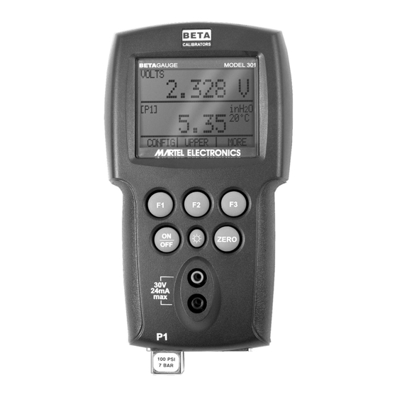
2.1 Calibrator Display The Calibrator Display consists of two regions: The menu bar (located along the bottom of the screen) is used to access a menu system. The main display (the rest) consists of up to three process measurement sub-regions. These sub-regions will henceforth be referred to as the UPPER, MIDDLE and LOWER displays. - Page 8 With a single display the following modes are available: P[1] = Pressure on left side sensor. [EXT] = Pressure with external pressure module. P[1] ST = Switch Test with left side sensor. [EXT] ST = Switch Test with external pressure module. mA = Milliamps measure without loop power.
- Page 9 Figure 4 Menu Map...
-
Page 10: Using The Backlight
2.2 Using the Backlight The backlight is controlled by the dedicated backlight key. It toggles on and off when the key is pressed; this is one of the few functions that cannot be controlled by the serial interface. 2.3 Using the Zero Function When the ZERO_KEY is pressed, the calibrator will zero the current display if a pressure mode is selected, and the pressure is within the zero limit. - Page 11 2.4.2 Locking and Unlocking Configurations Use the LOCK CFG or UNLOCK CFG option of the Configuration Lock Menu to lock or unlock the display configuration. When the LOCK CFG option is chosen the menu display returns home and the CONFIG option on the Main Menu indicates that it is locked.
- Page 12 Use the arrow keys to select the number of minutes before the calibrator turns off or disable auto shut-off by scrolling all the way down. Use the AUTO OFF DONE option to set the parameters and return home. The auto shut off time is reset whenever a key is pressed.
-
Page 13: Measuring Pressure
3. Measuring Pressure To measure pressure, connect the calibrator using an appropriate fitting. Choose a pressure setting for the display being used. The calibrator is equipped with one internal sensor and many optional external Pressure Modules are available. Be sure to choose the sensor based on working pressures and accuracy. -
Page 14: Measuring Current
Figure 6 4. Measuring Current To measure current use the input terminals in the front of the calibrator. Select the mA function on one of the displays. Current is measured in mA and percentage of range. The range on the calibrator is set to 0% at 4 mA and 100% at 20 mA. For example: If the current measured is displayed as 75% then the mA value is 16 mA. -
Page 15: Measuring Voltage
5. Measuring Voltage To measure voltage use the input terminals in the front of the calibrator. Select the Volts function on one of the displays. The calibrator can measure up to 30V. Figure 8... -
Page 16: Performing A Pressure Switch Test
6. Performing a Pressure Switch Test Pressure switch under test Figure 10 To perform a switch test, follow these steps: 1. Change the setup to Setup 4 (default switch test). Setup 4: The upper display is set to [P1] ST, all other displays are off. Important NOTE: The pressure Switch Test can be performed with the following functions[P1] ST, or EXT ST. - Page 17 5. Apply pressure with the pump slowly until the switch opens. Important NOTE: In the switch test mode the display update rate is increased to help capture changing pressure inputs. Even with this enhanced sample rate pressurizing the device under test should be done slowly to ensure accurate readings. 6.
-
Page 18: Calibrating Transmitters
9. Press the “NEW TEST” option to clear the data and perform another test. 10. Press the “DONE” option to end the test and return to the standard pressure setting. Example: [P1] ST will return to [P1]. Important NOTE: The previous example uses a normally closed switch. The basic procedure is still the same for a normally open switch, the display will just read “OPEN”... -
Page 19: Calibrating A Pressure-To-Current Transmitter
7.2 Calibrating a Pressure-to-Current Transmitter To calibrate a pressure-to-current transmitter (P/I), perform the following steps: 1. Connect the calibrator and the pump to the transmitter. 2. Apply pressure with the pump. 3. Measure the current output of the transmitter. 4. Ensure the reading is correct. If not, adjust the transmitter as necessary. Figure 11. -
Page 20: Percent Error Function
7.3 Percent Error Function The calibrator features a unique function which can calculate pressure vs. milliamp error as a percentage of the 4 to 20 mA loop span. The percent error mode uses all 3 screens and has a unique menu structure. It simultaneously displays pressure, mA and percent error. - Page 21 4. LOOP POWER can be toggled on/off, select NEXT when done. 5. Use SELECT to toggle through the UNIT options, and select NEXT to move on. 6. Use the ↑ and ↓ arrows to set the 100% point of the desired pressure range, select DONE SET when finished.
-
Page 22: Minimum And Maximum Storage Capacity
7. Again, use the arrows to set 0% point and select DONE SET when finished and the %ERROR mode will be ready to use. Note: The 0% and 100% point will be saved in non-volatile memory until they are changed again by the user for the internal sensors, and external pressure modules. When using an external module the 0% and 100% are set to low and full scale of the module until the user changes it, or if it was previously saved. -
Page 23: Factory Setups
9. Factory Setups The Calibrator is loaded with five factory setups. These setups are shown below. Setup 1: The upper display is set to [P1] mode and the middle is set to mA, lower is off. Setup 2: The upper display is set to [EXT] mode and the middle is set to mA, lower is off. Setup 3: The upper display is set to [P1] mode and the middle is set to [VOLTS] mode, lower is off. -
Page 24: Remote Operation
NOTE: To use the remote control option a custom RS-232 cable must be purchased from Martel (LEM232). To contact Martel refer to Section 1.1 of this manual. With this connection the user can write programs on a PC, with Windows languages like Visual Basic to operate the calibrator, or use a Windows terminal, such as Hyper Terminal, to enter single commands. - Page 25 Figure 13. Calibrator-to-Computer Connection 10.2 Setting up the RS-232 Port for Remote Control Note: The RS-232 connection cable should not exceed 15m unless the load capacitance measured at connection points is less than 2500pF. Serial parameter values: 9600 baud 8 data bits 1 stop bit no parity Xon/Xoff...
-
Page 26: Changing Between Remote And Local Operation
10.3 Changing Between Remote and Local Operation There are three modes of operation of the calibrator, Local, Remote, and Remote with Lockout. Local mode is the default mode. Commands may be entered using the keypad on the calibrator or using a computer. In Remote mode the keypad is disabled, and commands may only be entered using a computer, but choosing [GO TO LOCAL] from the menu on the calibrator display will restore keypad operation. - Page 27 10.4.2 Character Processing The data entered into the calibrator is processed as follows: • ASCII characters are discarded if their decimal equivalent is less than 32 (space), except 10 (LF) and 13 (CR): • Data is taken as 7-bit ASCII •...
-
Page 28: Remote Commands And Error Codes
10.5 Remote Commands and Error Codes The following tables list all commands, and their descriptions, that are accepted by the calibrator. Table 5: Common Commands Command Description *CLS (Clear status.) Clears the error queue. *IDN? Identification query. Returns the manufacturer, model number, and firmware revision level of the Calibrator. - Page 29 VAL? Returns the measured values ZERO_MEAS Zeros the pressure module ZERO_MEAS? Returns the zero offset of the pressure module Table 7: Parameter units Units Meaning milliamps of current Voltage in volts Pressure in pounds per square-inch INH2O4C Pressure in inches of water at 4°C INH2O20C Pressure in inches of water at 20°C CMH2O4C...
-
Page 30: Entering Commands
Table 8: Error Codes Error Number Error Description A non-numeric entry was received where it should be a numeric entry Too many digits entered Invalid units or parameter value received Entry is above the upper limit of the allowable range Entry is below the lower limit of the allowable range A required command parameter was missing An invalid command parameter was received... - Page 31 *IDN? will return BETA, 301, 0, 1.00 10.6.2 Calibrator Commands DAMP Turns the dampening function on or off. For example: If you send DAMP ON this will turn the dampening function on. DAMP? Returns the current state of the dampening function. For example: If you send DAMP? It will return ON if the dampening function is on.
- Page 32 To set loop power on send ERROR_LOOP ON. ERROR _LOOP? Returns the current state of loop power in percent error mode. For example: If you send ERROR_LOOP? It will return ON if loop power is on in error mode. ERROR_ MODE Turns percent error mode on and off.
- Page 33 ST_P1,P1,NONE HI_ERR Sets the 100% point for the percent error mode calculation in the current engineering units. For example: To set the 100% point to 100 psi send HI_ERR 100. HI_ERR? Returns the 100% point for the percent error mode calculation. For example: If the 100% point is set to 100 psi, HI_ERR? would return 1.000000E+02, PSI .
- Page 34 PRES_UNIT? Returns the pressure unit used when measuring pressure for each of the 3 displays. REMOTE Puts the calibrator in remote mode. From the remote mode the user can still use the keypad to get back to local unless the command LOCKOUT was entered before REMOTE.
-
Page 35: Specifications
11. Specifications (18 °C to 28 °C unless otherwise noted.) General Instrument Setup Recall 5; last used on power-up Environmental Operating Temperature -10 °C to +50 °C Storage Temperature -20 °C to +60 °C Power Requirements 6.0 VDC Battery Four (4) standard AA cells Battery Life >... -
Page 36: Warranty
Receiving Department to accept the shipment. Any package not so marked will not be accepted and will be returned to the shipper. Martel will not be responsible for damage as a result of poor return packaging. Out of warranty repairs and recalibration will be subject to specific charges. - Page 40 Tel: (603) 434-1433 800-821-0023 Fax: (603) 434-1653 Martel Electronics 3 Corporate Park Drive Derry, NH 03038 0219409 Rev D 11/10...
Need help?
Do you have a question about the BETAGAUGE 301 and is the answer not in the manual?
Questions and answers