Advertisement
Quick Links
Advertisement

Subscribe to Our Youtube Channel
Related Manuals for Award EMB-M5


Summary of Contents for Award EMB-M5
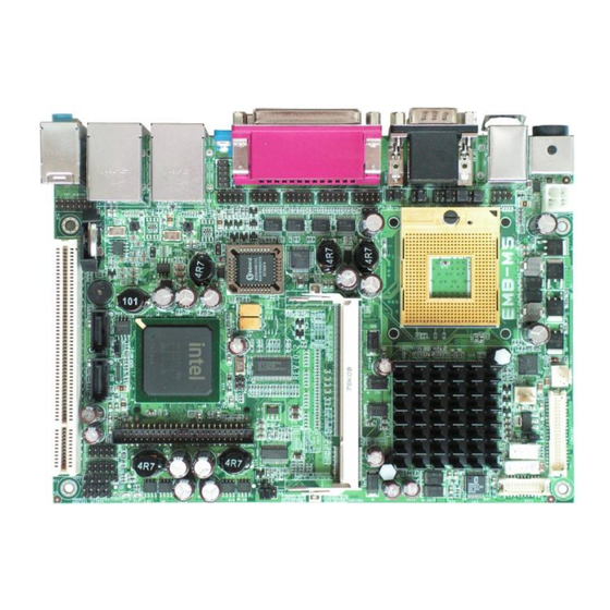
- Page 1 EMB-M5 Intel® Core™2 Duo 945GME Embedded Main-Board User's Manual Version 1.0...
- Page 2 The material contained herein is for informational purposes only. Acknowledgments Award is a registered trademark of Award Software International, Inc. IBM, PS/2 is trademarks of International Business Machines Corporation. Intel Pentium M is registered trademarks of Intel Corporation.
- Page 3 VGA Connector ..................25 INT_VGA Connector ................26 INT_KBMS Connector ................26 DC_IN1 Connector ................27 DC_IN2 Power Connector ..............27 CPU Fan Power Connector ..............27 System FAN Power Connector ............28 DRVPWR Connector ................28 EMB-M5 User`s Manual...
- Page 4 CPU Feature ..................49 Delay Prior to Thermal ..............49 Limit CPUID Max Val ............... 49 C1E Function ................... 49 Execute Disabled Bit ................ 49 Hard Disk Boot Priority ................ 50 Bootable Add-in Cards ..............50 Virus Warning ..................51 EMB-M5 User`s Manual...
- Page 5 IDE HDD Block Mode ..............60 On-Chip Primary PCI IDE ..............61 IDE Primary/Secondary, Master/Slave PIO ........61 IDE Primary/Secondary, Master/ Slave UDMA ....... 61 On-Chip Secondary PCI IDE ............. 61 On-Chip Serial ATA ................62 SATA Mode ..................64 EMB-M5 User`s Manual...
- Page 6 Video Off In Suspend ................. 77 Suspend Type..................77 MODEM Use IRQ ................77 Suspend Mode ..................77 HDD Power Down ................78 Soft-Off by PWR-BTTN ............... 78 CPU THRM-Throttling ................78 Wake-Up by PCI card ................78 EMB-M5 User`s Manual...
- Page 7 3.13 S & E ............... 90 ETUP 3.14 E ..............90 ITHOUT AVING CHAPTER 4 APPENDIX ..............91 A. I/O P ..............92 DDRESS B. I (IRQ) ............93 NTERRUPT EQUEST INES C. POST B ..................94 EMB-M5 User`s Manual...
- Page 8 Contents This page is intentionally left blank viii EMB-M5 User`s Manual...
- Page 9 This manual is designed to give you information on the M5 Industrial Main Board. The topics covered in this manual are as follows: Features Specification Jumper setting and Connectors BIOS Setup Appendix EMB-M5 User`s Manual...
- Page 10 Chapter 1 Features & Specifications ....................3 EATURES ..................4 PECIFICATIONS EMB-M5 User`s Manual...
- Page 11 Dual GbE LAN design maximized the communication bandwidth for both internet and intranet connection. Root Boot and Wake Up on LAN supported. High-Definition Audio with internal connection and external audio jack. LCD Brightness control with Software ready for Windows XP/2K. EMB-M5 User`s Manual...
- Page 12 1 x Parallel port supports SPP/ECP/EPP mode. (25-Pins D-Sub Female on Rear). 1 x IrDA port; (5-pins pin-header with +5V powered). Four USB2.0 ports for internal or front panel connection. (2x5 pin-header/ 2mm pitch). EMB-M5 User`s Manual...
- Page 13 RealTek ALC888 High-Definition Audio chip on-board. Two Audio-Jack on rear for Audio Line-OUT and MIC. One 14-pins pin-header to provide internal audio device connection or surrounding speaker connection. DIO: 8-bits Digital I/O control. Support 8-In, 8-out or 4-In/4-out. EMB-M5 User`s Manual...
- Page 14 BIOS: Award Standard PnP Flash BIOS 6.0. 8Mbit FlashROM with BootBlock for Fail-safe. BIOS utility for field update. VBIOS and LAN remote Boot Agent integrated. PCI Expansion Slot: One PCI 120-pins connector and support ETOP Riser card up to 3 PCI-slots.
- Page 15 Chapter 2 Jumper setting & Connectors 2.1 J M5 ................. 8 UMPERS ON THE 2.2 C M5 ..............14 ONNECTORS ON THE EMB-M5 User`s Manual...
- Page 16 JP4: Clear CMOS RAM Data..............10 JP5: CF Card Mode Selection ...............11 JP6, JP7: COM Power Selection ............11 JP8: COM6 Power Pin (Pin9) ..............11 LCDPWR: LCD PANEL Power Selection ..........12 AT MODE: AT Mode Selection .............12 COM2MODE: RS232/RS422/RS485 ............13 EMB-M5 User`s Manual...
- Page 17 Jumper Locations on the M5 EMB-M5 User`s Manual...
- Page 18 (3) Short the pin2 and pin3 for three seconds, (4) Put Jumper cap back to pin1 & 2. (5) Turn on your computer, (6) Hold Down <Delete> during boot up and enter BIOS setup to enter your preferences. COMS NORM EMB-M5 User`s Manual...
- Page 19 JP6, JP7 can be used to select the COM supple power: +5V, Ring-IN or +12V. JP6: COM1 Pin9 power or Ring-IN JP7: COM2 pin9 power or Ring-IN +12V JP8: COM6 Power Pin (Pin9) JP8: COM6 Pin9 power. +12V EMB-M5 User`s Manual...
- Page 20 +5V.The default setting is on +3.3V.User need to check the LCD panel spec and adjust this jumper to make Panel work in specified power rail. This Jumper serves LVDS LCD connector. LCDPWR +3.3V AT MODE: AT Mode Selection AT Mode ATX Mode EMB-M5 User`s Manual...
- Page 21 COM3, COM4. COM5 and COM6 support diffused RS232 protocol. The Protocols of COM2 can be set up through jumpers. COM2MODE: COM2 Protocols selection. The pin-out for each mode is illustrated on next chapter. COM2MODE1 I/F TYPE RS-232 RS-422 RS-485 EMB-M5 User`s Manual...
- Page 22 LAN- GBE Connectors ................29 LAN RJ45 LED1, 2 ................. 30 Audio Connectors ................30 INT_AUDIO Connector ................. 31 LVDS LCD Connector ................32 DVI Connector ..................33 DIO Connector ..................34 SATA1, SATA2 Connectors ..............34 CF-II Connector ..................35 EMB-M5 User`s Manual...
- Page 23 Connector Locations on the M5 EMB-M5 User`s Manual...
- Page 24 Pin # PWR-BTN IDE Hard Disk LED Connector This connector connects to the hard drive activity LED on control panel. This LED will flash when the HDD is being accessed. IDE LED Signal Name Pin # HDDLED EMB-M5 User`s Manual...
- Page 25 Orientation is not required when making a connection to this header. RESET Signal Name Pin # Reset Ground KEYLOCK Switch The keylock switch, when closed, will disable the keyboard function. RESET Signal Name Pin # KEYLOCK EMB-M5 User`s Manual...
- Page 26 BACKLIGHT Connector Pin # Signal Name +12V Brightness ON/OFF TV-OUT Connector Pin # Signal Name LUMA CHOMA CVBS EMB-M5 User`s Manual...
- Page 27 IRDA Connector This connector is used for an IRDA connector for wireless communication. +5V IRTX IRRX IrDA Pin # Signal Name CIRRX GND IR-RX Ground IR-TX EMB-M5 User`s Manual...
- Page 28 Host data 0 Host data 15 Ground Ground Host IOW Ground Host IOR Ground IOCHRDY Host PU 0 DACK Ground IRQ14 No connect Address 1 P66DET Address 0 Address 2 Chip select 1 Chip select 3 Activity LED EMB-M5 User`s Manual...
- Page 29 TX+ (422/485) RXD, Receive data RX+ (422) TXD, Transmit data DTR, Data terminal ready RX- (422) GND, ground N.C. DSR, Data set ready RTS, Request to send N.C. N.C. CTS, Clear to send N.C. +5V,Ring-IN or +12V EMB-M5 User`s Manual...
- Page 30 Pin # RS232 Mode Signal Name DCD, Data carrier detect RXD, Receive data TXD, Transmit data DTR, Data terminal ready GND, ground DSR, Data set ready RTS, Request to send CTS, Clear to send Ring-IN EMB-M5 User`s Manual...
- Page 31 DTR, Data terminal ready GND, ground DSR, Data set ready RTS, Request to send CTS, Clear to send +5V, +12V Pin9 is power pin to support devices required power. The voltage can be selected by jumper JP8. EMB-M5 User`s Manual...
- Page 32 The LPT parallel port is a standard DSUB 25-pins Female connector. It can be configured as EPP or ECP or SPP mode. Signal Name Pin # Pin # Signal Name Strobe AUTOFD DATA0 ERROR DATA1 INIT SLIN DATA2 DATA3 DATA4 DATA5 DATA6 DATA7 BUSY SLCT EMB-M5 User`s Manual...
- Page 33 Pin # Signal Name Keyboard/Mouse data Keyboard/Mouse clock VGA Connector The pin assignments of VGA CRT connector are as follows: Signal Name Pin # Pin # Signal Name Green Blue N.C. N.C. N.C. DDC_DATA HSYNC VSYNC DDC_CLK EMB-M5 User`s Manual...
- Page 34 Signal Name GREEN BLUE HSYNC DDC_DATA VSYNC DDC_CLK INT_KBMS Connector KBMS is for internal input devices or MSR connection. The pin out is listed as below: Signal Name Pin # Pin # Signal Name KBDAT MSCLK KBCLK MSDAT EMB-M5 User`s Manual...
- Page 35 If you already have external +12V power input connected on DC_IN1, please leave DC_IN2 unconnected. Pin # Signal Name +12V DC_IN2 +12V CPU Fan Power Connector This is a 3-pin header for the CPU fan. Pin # Signal Name 3 2 1 Ground +12V CPUPWM EMB-M5 User`s Manual...
- Page 36 The pin out is listed as below: Signal Name Pin # Pin # Signal Name +12V USB56 USB78 Connectors The following table shows the pin outs of the USB56 USB78 connectors. USB5,USB6 Signal Name USB7,USB8 Pin# N.C. Ground USB- USB+ EMB-M5 User`s Manual...
- Page 37 LAN- GBE Connectors This connector is for the 10/100/1000Mbps Ethernet capability. The figure below shows the pin out assignments of this connector and its corresponding input jack. Pin # Signal Name MDI0+ MDI0- MDI1+ MDI1- MDI2+ MDI2- MDI3+ MDI3- EMB-M5 User`s Manual...
- Page 38 STATUS YELLOW Link Disconnected FLASH Packets TX/RX SPEED MODE ORANGE 1000 Mbps GREEN 100 Mbps 10 Mbps Audio Connectors After install onboard audio driver, you may connect speaker to Line Out jack, microphone to MIC In jack. EMB-M5 User`s Manual...
- Page 39 INT_AUDIO Connector Pin # Signal Name LINE-IN-L LINE-IN-R LINEOUT-L LINEOUT-R MIC1-IN-L MIC1-IN-R LFE OUT CENTER OUT SURR OUTL SURR OUTR EMB-M5 User`s Manual...
- Page 40 +12V LCDVDD 5V/3.3V LCDVDD 5V/3.3V BCKLITE_ON BRIGHTNES LVDS_GND LVDS_GND CHB_TX0+ CHA_TX0+ CHB_TX0- CHA_TX0- LVDS_GND LVDS_GND CHB_TX1+ CHA_TX1+ CHB_TX1- CHA_TX1- LVDS_GND LVDS_GND CHB_TX2+ CHA_TX2+ CHB_TX2- CHA_TX2- LVDS_GND LVDS_GND CHB_TXC+ CHA_TXC+ CHB_TXC- CHA_TXC- LVDS_GND LVDS_GND CHB_TX3+ CHA_TX3+ CHB_TX3- CHA_TX3- EMB-M5 User`s Manual...
- Page 41 DVI Connector Signal Signal Name Name TCLK+ TDC1+ TCLK- TDC1- TDC0+ TDC2+ TDC0- TDC2- CLOCK DATA DVI_PLUG EMB-M5 User`s Manual...
- Page 42 DIO port supports 8 digital I/O bits. Each bit can be configured as Input or output individually. All bits are 5V tolerant. Signal Name Pin # Pin # Signal Name DIO_0 DIO_4 DIO_1 DIO_5 DIO_2 DIO_6 DIO_3 DIO_7 SATA1, SATA2 Connectors Pin # Signal Name SATATX+ SATATX- SATARX- SATARX+ EMB-M5 User`s Manual...
- Page 43 Signal Name PDD3 PDD4 PDD5 PDD6 PDD7 PCS1- PDA2 PDA1 PDA0 PDD0 PDD1 PDD2 N.C. N.C. N.C. PDD11 PDD12 PDD13 PDD14 PDD15 PCS3- N.C. PDIOR- PDIOW- IRQ14 MST#_SLV N.C. PST1- PIORDY PDDREQ PDDACK- CF_LED- N.C. PDD8 PDD9 PDD10 EMB-M5 User`s Manual...
- Page 44 This page is intentionally left blank EMB-M5 User`s Manual...
- Page 45 Chapter 3 BIOS Setup This chapter describes the different settings available in the Award BIOS that comes with the M5 CPU card. The topics covered in this chapter are as follows: 3.1 M .................. 41 3.2 S CMOS F ............43...
- Page 46 BIOS Introduction This Chapter discusses Award™ Setup program built into the M5 BIOS. The Setup program allows users to modify the basic system configuration. This special information is then stored in battery-backed RAM so that it retains the Setup information when the power is turned off.
- Page 47 F5 key Load previous values from CMOS F6 key Load the fail-safe defaults from BIOS default table F7 key Load the optimized defaults F10 key Save all the CMOS changes and exit Navigating through the menu bar EMB-M5 User`s Manual...
- Page 48 To this end, we strongly recommend that you avoid making any changes to the chipset defaults. These defaults have been carefully chosen by both Award and M5 manufacturer to provide the absolute maximum performance and reliability. Even a seemingly small change to the chipset setup has the potential for causing you to use the override.
- Page 49 Use this menu for basic system configuration. Advanced BIOS Features Use this menu to set the Advanced Features available on your system. Advance Chipset Features Use this menu to change the values in the chipset registers and optimize your system's performance. EMB-M5 User`s Manual...
- Page 50 Load Optimized Defaults Use this menu to load the BIOS default values that are factory settings for optimal performance system operations. While Award has designed the custom BIOS to maximize performance, the factory has the right to change these defaults to meet their needs.
- Page 51 Each category includes no, one or more than one setup items. Use the arrow keys to highlight the item and then use the <PgUp> or <Pg Dn> keys to select the value you want in each item. Phoenix-Award BIOS CMOS Setup Utility Standard CMOS Features Date (mm :dd: yy)
- Page 52 All, but Disk/Key Base Memory Displays the amount of conventional memory detected during boot up Extended Memory Displays the amount of extended memory detected during boot up Total Memory Displays the total memory available in the system EMB-M5 User`s Manual...
- Page 53 The IDE adapters control the hard disk drive. Use a separate sub menu to configure each hard disk drive. Figure 3 shows the IDE Channel 0 / Channel 1 master sub menu. Phoenix-Award BIOS CMOS Setup Utility IDE Channel 0 Master IDE HDD Auto-Detection...
- Page 54 Min = 0 **** Warning: Setting a value Max = 65535 of 65535 means no hard disk Landing zone Min = 0 **** Max = 65535 Sector Min = 0 Number of sectors per track Max = 255 EMB-M5 User`s Manual...
- Page 55 The system boot will not be halted for a disk error; it will stop for all other errors. All, But Disk/Key The system boot will not be halted for a key- board or disk error; it will stop for all others. (default) EMB-M5 User`s Manual...
- Page 56 This section allows you to configure your system for basic operation. You have the opportunity to select the system’s default speed, boot-up sequence, keyboard operation, shadowing and security. Phoenix-Award BIOS CMOS Setup Utility Advanced BIOS Features ►CPU Features [Press Enter] Item Help ►Hard Disk Boot Priority...
- Page 57 CPU Feature Phoenix-Award BIOS CMOS Setup Utility CPU Feature Delay Prior to Thermal Min] Item Help Limit CPUID MaxVal [Disabled] ► C1E Function [Auto] Menu Level Execute Disabled Bit [Enabled] ↑↓← → :Move Enter: Select +/-/PU/PD: Value F10:Save Esc: Exit...
- Page 58 Hard Disk Boot Priority Phoenix-Award BIOS CMOS Setup Utility Hard Disk Boot Priority 1.Bootable Add-in Cards Item Help ► Menu Level Use <> or <> to select a device, then press <+> to move it up, or <-> to move it down the list.
- Page 59 This field is used to enable or disable the CPU’s L3 cache. The choice: Enabled (default), Disabled. Quick Power On Self Test Allows the system to skip certain tests while booting. This will decrease the time needed to boot the system. Enabled Enable quick POST(default) Disabled Normal POST EMB-M5 User`s Manual...
- Page 60 Boot Up Num Lock Status Selects power on state for Num Lock. The choice: On, Off (default). Gate A20 Option The choice: Normal: A pin in the keyboard controller controls GateA20. Fast (default): Lets chipset control GateA20. EMB-M5 User`s Manual...
- Page 61 Sets the delay time after the key is held down before it begins to repeat the keystroke. The choice: 250 (default), 500, 750, and 1000. Typematic Delay (Msec) ….. [ ….. [ ] ….. [ ] 1000 ….. [ ] : Move Enter: Accept ESC: Abort EMB-M5 User`s Manual...
- Page 62 OS Select For DRAM > 64MB Select OS2 only if you are running OS/2 operating system with greater than 64MB of RAM on the system. The choice: Non-OS2 (default), OS2. Report No FDD For WIN 95 The choice: No (default), Yes. EMB-M5 User`s Manual...
- Page 63 The only time you might consider making any changes would be if you discovered that data was being lost while using your system. Phoenix-Award BIOS CMOS Setup Utility Advanced Chipset Features DRAM Timing Selectable [By SPD]...
- Page 64 The choice: Auto (default), 2, 3,4,5,6. Precharge dealy (tRAS) The choice: Auto (default), 4,5,6,7,8,9,10,11,12,13,14,15. System Memory Frequency The choice: Auto (default), 533MHz, 667MHz SLP_S4#Assertoin Width Set SLP_S4# pin. The choice: 4 to5 Sec (default), 3 to 4Sec, 2to 3Sec, 1to2Sec. EMB-M5 User`s Manual...
- Page 65 This field shows the current DVMT mode. The choice: FIXED, DVMT (default), BOTH DVMT / FIXED Memory Size This field is used to select the graphics memory size used by DVMT/ Fixed mode. The choice: 64MB, 128MB (default), 224MB EMB-M5 User`s Manual...
- Page 66 Auto(defau NTSC_M NTSC_M_J NTSC_433 NTSC_N PAL_B PAL_G PAL_D PAL_H PAL_I PAL_M PAL_N PAL_60 SECAM_L SECAM_L1 SECAN_B SECAN_D SECAN_G SECAN_H SECAN_K SECAN_K1 Lan1 Chip Control The choice: Enabled (default), Disabled. Lan2 Chip Control The choice: Enabled (default), Disabled. EMB-M5 User`s Manual...
- Page 67 3.5 Integrated Peripherals Phoenix-Award BIOS CMOS Setup Utility Integrated Peripherals ► On Chip IDE Device [Press Enter] Item Help ► Onboard Device [Press Enter] ► Super IO Device ► [Press Enter] Menu Level Onboard Serial Port 3 [3E8] Serial Port 3 Use IRQ...
- Page 68 On Chip IDE Device Phoenix-Award BIOS CMOS Setup Utility On Chip IDE Device IDE HDD Block Mode [Enabled] Item Help On-Chip Primary PCI IDE [Enabled] ► IDE Primary Master PIO [Auto] Menu Level IDE Primary Slave PIO [Auto] If your IDE hard...
- Page 69 The choice: Disabled, Auto (default) On-Chip Secondary PCI IDE These fields allow you to enable or disable the primary and secondary IDE controller. Select disabled if you want to add a different hard drive controller. The choice: Enabled (default), Disabled. EMB-M5 User`s Manual...
- Page 70 Means SATA is operating in legacy mode.(Figure 14) Auto This is the default setting. The choice: Disabled, Auto (default), Combined Mode, Enhanced Mode, SATA Only. Phoenix-Award BIOS CMOS Setup Utility On Chip IDE Device IDE HDD Block Mode [Enabled] Item Help...
- Page 71 When you press [Disabled] or [Auto] on this item will show: [Auto] is the default choice. Phoenix-Award BIOS CMOS Setup Utility On Chip IDE Device IDE HDD Block Mode [Enabled] Item Help On-Chip Primary PCI IDE [Enabled] ► IDE Primary Master PIO...
- Page 72 When you press [Combined Mode] on this item will show: Phoenix-Award BIOS CMOS Setup Utility On Chip IDE Device IDE HDD Block Mode [Enabled] Item Help On-Chip Primary PCI IDE [Enabled] ► IDE Primary Master PIO [Auto] Menu Level IDE Primary Slave PIO...
- Page 73 When you press [Enhanced Mode] on this item will show: Phoenix-Award BIOS CMOS Setup Utility On Chip IDE Device IDE HDD Block Mode [Enabled] Item Help On-Chip Primary PCI IDE [Enabled] ► IDE Primary Master PIO [Auto] Menu Level IDE Primary Slave PIO...
- Page 74 When you press [SATA Only] on this item will show: Phoenix-Award BIOS CMOS Setup Utility On Chip IDE Device IDE HDD Block Mode [Enabled] Item Help On-Chip Primary PCI IDE [Enabled] ► IDE Primary Master PIO [Auto] Menu Level IDE Primary Slave PIO...
- Page 75 On board Device Phoenix-Award BIOS CMOS Setup Utility Onboard Device USB Controller [Enabled] Item Help USB 2.0 Controller [Enabled] ► USB Keyboard Support [Disabled] Menu Level Azalia/AC97 Audio Select [Auto] ↑↓← → :Move Enter: Select +/-/PU/PD: Value F10:Save Esc: Exit F1:General Help...
- Page 76 Super IO Device Phoenix-Award BIOS CMOS Setup Utility Super IO Device Onboard Serial Port 1 [3F8/IRQ4] Item Help Onboard Serial Port 2 [2F8/IRQ3] ► UART Mode Select [Normal] Menu Level x RxD , TxD Active Hi, Lo x IR Transmission Delay...
- Page 77 This item allows you to select which mode for the Onboard Serial Port 2. The choice: IrDA, ASKIR, Normal (default) If UART Mode Select is IrDA and ASKIR will show: Phoenix-Award BIOS CMOS Setup Utility Super IO Device Onboard Serial Port 1 [3F8/IRQ4]...
- Page 78 Sets the parallel port up as an Enhanced Capabilities Port. This setting requires the use of a DMA channel If Parallel Port Mode Select is [SPP] and [Normal] will show: Phoenix-Award BIOS CMOS Setup Utility Super IO Device Onboard Serial Port 1...
- Page 79 If Parallel Port Mode Select is [EPP] will show: Phoenix-Award BIOS CMOS Setup Utility Super IO Device Onboard Serial Port 1 [3F8/IRQ4] Item Help Onboard Serial Port 2 [2F8/IRQ3] ► UART Mode Select [IrDA] Menu Level RxD , TxD Active...
- Page 80 If Parallel Port Mode Select is [ECP] will show: Phoenix-Award BIOS CMOS Setup Utility Super IO Device Onboard Serial Port 1 [3F8/IRQ4] Item Help Onboard Serial Port 2 [2F8/IRQ3] ► UART Mode Select [IrDA] Menu Level RxD , TxD Active...
- Page 81 If Parallel Port Mode Select is [ECP+EPP] will show: Phoenix-Award BIOS CMOS Setup Utility Super IO Device Onboard Serial Port 1 [3F8/IRQ4] Item Help Onboard Serial Port 2 [2F8/IRQ3] ► UART Mode Select [IrDA] Menu Level RxD , TxD Active...
- Page 82 The choice: Disabled, 4F8, 4E8 (default). Serial Port 6 Use IRQ This is used to select an IRQ for the onboard serial port 6. The choice: IRQ3, IRQ4, IRQ5, IRQ7 (default), IRQ10, IRQ11 Watch Dog Timer Select The choice: Disabled (default), Enable EMB-M5 User`s Manual...
- Page 83 The Power Management Setup allows you to configure you system to most effectively save energy while operating in a manner consistent with your own style of computer use. Phoenix-Award BIOS CMOS Setup Utility Power Management Setup ►PCI Express PM Function...
- Page 84 PCI Express PM Function Phoenix-Award BIOS CMOS Setup Utility PCI Express PM Function PCI Express PME [Enabled] Item Help ► Menu Level ↑↓← → :Move Enter: Select +/-/PU/PD: Value F10:Save Esc: Exit F1:General Help F5:Previous Value F6:Fail-Safe Defaults F7:Optimized Default PCI Express PME The choice: Enabled (default), Disabled.
- Page 85 This field specifies the length of time of system inactivity while in full power on state before the computer enters suspend mode and motivates the enable 'Wake up Events in Doze & Standby' / 'PM Events'. The choice: 1Min, 2Min, 4Min, 8Min, 12Min, 20Min, 30Min, 40Min,1Hour, Disable (default). EMB-M5 User`s Manual...
- Page 86 This field allows you to select the CPU THRM-Throttling rate. The choice: 75.0%, 50.0% (default), 25.0%. Wake-Up by PCI card Enable/Disable PCI PME wake up function. The choice: Enabled (default), Disabled. Power On by Ring Enable/Disable Power On By Ring function. The choice: Enabled (default), Disabled. EMB-M5 User`s Manual...
- Page 87 Key in a DEC number: wwww : Move Enter: Accept ESC:Abort Primary/ Secondary IDE 0/1 When Enabled, the system will resume from suspend mode if Primary IDE 0 (1) or Secondary IDE 0 (1) is active. The choice: Enabled, Disabled (default) EMB-M5 User`s Manual...
- Page 88 When Enabled, the system will resume from suspend mode if FDD, COM port, or LPT port is active. The choice: Enabled, Disabled (default). PCI PIRQ [A-D] # When Enabled, the system will resume from suspend mode if interrupt occurs. The choice: Enabled, Disabled (default). EMB-M5 User`s Manual...
- Page 89 This section covers some very technical items and it is strongly recommended that only experienced users should make any changes to the default settings. Phoenix-Award BIOS CMOS Setup Utility PnP/PCI Configuration Init Display First [PCI Slot]...
- Page 90 BIOS automatically assigns them. The choice: Auto (ESCD) (default), Manual. If Resources Controlled By is [Manual], can choice IRQ Resource: Phoenix-Award BIOS CMOS Setup Utility PnP/PCI Configuration Init Display First [PCI Slot] Item Help...
- Page 91 This item allows you to determine the IRQ assigned to the ISA bus and is not available to any PCI slot. Phoenix-Award BIOS CMOS Setup Utility IRQ Resource IRQ-3 assigned to...
- Page 92 This BIOS feature determines if your graphics card should allow VGA palette snooping by a fixed function display card. The choice: Enabled, Disabled (default). INT Pin 1/2/3/4/5/6/7/8 Assignment The choice: Auto (default),3,4,5,7,9,10,11,12,14,15. Maximum Payload Size The choice: 128 (default), 256,512,1024,2048,4096. EMB-M5 User`s Manual...
- Page 93 CPU temperature, FAN speed and voltages. It is recommended that you contact with your motherboard supplier to get proper value about your setting of the CPU temperature. Phoenix-Award BIOS CMOS Setup Utility PC Health Status CPU Warning Temperature [Disabled] Item Help Current System Temp.
- Page 94 CPU FAN Speed Shows speed. CPU Fan CHASSIS Fan Speed Shows CHASSIS speed Shutdown Temperature Select the CPU over-heated shutdown temperature. C/140F, 65C/149F, 70C/158F, The choice: Disabled (default), 60 75C/167F EMB-M5 User`s Manual...
- Page 95 3.9 Frequency/Voltage Control Phoenix-Award BIOS CMOS Setup Utility Frequency/Voltage Control Spread Spectrum [Disabled] Item Help ► Menu Level ↑↓← → :Move Enter: Select +/-/PU/PD: Value F10:Save Esc: Exit F1:General Help F5:Previous Value F6:Fail-Safe Defaults F7:Optimized Default Spread Spectrum Leave this field in its default setting. Do not alter this setting unless advised by an engineer or technician.
- Page 96 3.11 Load Optimized Defaults When you press <Enter> on this item you get a confirmation dialog box with a message similar to: Phoenix-Award BIOS CMOS Setup Utility ►Stand CMOS Features ►Frequency/Voltage Control ►Advanced BIOS Features Load Fail-Safe Default ►Advance Chipset Features Load Optimized Default ►Integrated Peripherals...
- Page 97 A message will confirm the password will be disabled. Once the password is disabled, the system will boot and you can enter Setup freely. Phoenix-Award BIOS CMOS Setup Utility ►Stand CMOS Features ►Frequency/Voltage Control ►Advanced BIOS Features Load Fail-Safe Default ►Advance Chipset Features...
- Page 98 3.13 Save & Exit Setup Pressing <Enter> on this item asks for confirmation: Phoenix-Award BIOS CMOS Setup Utility ►Stand CMOS Features ►Frequency/Voltage Control ►Advanced BIOS Features Load Fail-Safe Default ►Advance Chipset Features Load Optimized Default ►Integrated Peripherals Set Supervisor Password SAVE to CMOS and EXIT (Y/N)? Y ►Power Management...
- Page 99 CHAPTER 4 Appendix A. I/O P ..............92 DDRESS B. I (IRQ) ............93 NTERRUPT EQUEST INES C. POST B ..................94 EMB-M5 User`s Manual...
- Page 100 Parallel Port #1(LPT1) 360 - 36F Network Ports 3B0 - 3BF Monochrome & Printer adapter 3C0 - 3CF EGA adapter 3D0 - 3DF CGA adapter 3F0h - 3F7h Floppy Disk Controller 3F8h - 3FFh Serial Port #1(COM1) EMB-M5 User`s Manual...
- Page 101 Serial Port #1 IRQ5 Reserved IRQ6 Floppy Disk Controller IRQ7 Parallel Port #1 IRQ8 Real Time Clock IRQ9 Software Redirected to Int 0Ah IRQ10 Reserved IRQ11 Reserved IRQ12 PS/2 Mouse IRQ13 80287 IRQ14 Primary IDE IRQ15 Secondary IDE EMB-M5 User`s Manual...
- Page 102 This beep code consists of a single long beep followed by two short beeps. The other code indicates that your DRAM error has occurred. This beep code consists of a single long beep repeatedly. EMB-M5 User`s Manual...
Need help?
Do you have a question about the EMB-M5 and is the answer not in the manual?
Questions and answers