Table of Contents
Advertisement
Quick Links
Chapter 1
INTRODUCTION
The NLX BX4 mainboard is a high-performance personal computer
®
®
®
mainboard based on Intel
Pentium
II processor. It combines Intel
740
®
®
graphics accelerator, YAMAHA
YMF740 enhanced audio, and Intel
82558
®
TM
10/100M Ethernet . The Pentium
II processor supports MMX
(Multime-
dia Extension) technology.
®
The mainboard uses the highly integrated Intel
82443BX chipset to support
the PCI/ISA and Green standards, and to provide the Host/AGP bridge. The
®
Intel
82371EB chipset integrates all system control functions such as ACPI
(Advanced Configuration and Power Interface). The ACPI provides more
Energy Saving Features for the OSPM(OS Direct Power Management)
®
function. The Intel
82371EB chipset also improves the IDE transfer rate by
supporting Ultra DMA/33 IDE that transfers data at the rate of 33MB/s.
The mainboard also supports the System Hardware Monitor Controller. This
function includes: CPU /power supply/chassis fan revolution detect, CPU/
system voltage monitor, system temperature monitor, and chassis intrusion
detect.
1-1
Advertisement
Table of Contents

Related Manuals for Award NLX BX4


Summary of Contents for Award NLX BX4
- Page 1 Chapter 1 INTRODUCTION The NLX BX4 mainboard is a high-performance personal computer ® ® ® mainboard based on Intel Pentium II processor. It combines Intel ® ® graphics accelerator, YAMAHA YMF740 enhanced audio, and Intel 82558 ® 10/100M Ethernet . The Pentium...
-
Page 2: Mainboard Features
1.1 Mainboard Features ® Slot 1 for Pentium II processor. Supports 233MHz, 266MHz, 300MHz, 333MHz, 350MHz, 400MHz, and faster. Core/Bus ratios are x2, x2.5, x3, x3.5, x4, x4.5, x5, x5.5, x6 and higher. Switching Voltage Regulator On-board switching mode DC-DC Step Down Regulator. ®... - Page 3 System Hardware Monitor ® This can be used with Intel LDCM to monitor system voltage, system temperature & fan rotation speed. This can also be used to monitor overall system status over the network. System temperature sensor: (TOP Tech) ® - detect Pentium II processor’s temperature.
- Page 4 ® Intel 82558 10/100M Ethernet. WFW baseline & NET PC specs compliant. ACPI Magic packet filtering to wake-up LAN. ARP & FLEXIBLE frame filtering. Software drivers are backwards compatible. Note: Requires an ATX power supply with 720mA 5VSB (5v Stand by). Rear Mainboard Connectors ®...
-
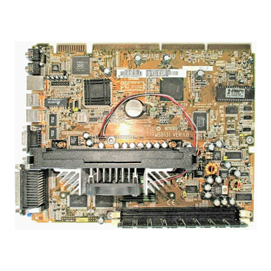
Page 5: Mainboard Layout
1.2 Mainboard Layout T: LPT T: mouse Joystick/ SPKR L-IN B: COM A RJ-45 MIDI Port keyboard COM B JMIC1 YAMAHA YMF740 Intel ® 82558 10/100M Ethernet Intel ® Graphics Accelerator PIIX4E FW82443BX JSOR1 BATT CPUFAN1 JBAT1 MS-6121... -
Page 6: Hardware Installation
Chapter 2 HARDWARE INSTALLATION ® ® The mainboard operates with Intel Pentium II processor with MMX technology. The mainboard uses a CPU Slot called Slot 1 for easy CPU installation and a DIP switch (SW1) to set the proper speed for the CPU. The CPU should always have a Heat Sink and a cooling fan attached to prevent overheating. -
Page 7: Cpu Installation Procedures
2.1-1 CPU Installation Procedures ® Different kinds of Pentium II processor that is currently used: the OEM ® version, the Boxed version, and Celeron . OEM Pentium II Processor has ® no Heat Sink, Fan and Heat Sink Support, the Boxed Pentium II Processor is provided with Heat Sink w/ fan and Heat Sink Support, while the Celeron... - Page 8 *Heat Sink Support Pin (HSSPIN) - Plastic pins inserted through the HSSBASE to secure it to the mainboard (2 required per Assembly). *Heat Sink Support Top Bar (HSSTOP) - Plastic bar that clips onto the HSSBASE through the fins on the ATX heatsink.
- Page 9 Step 1: Insert the Retention Mechanism Attach Mount at the bottom of the mainboard. Step 2: Install the Retention Mechanism. Look for the key on Slot 1, and match it with the Notch Key on the Retention Mechanism for proper direction. Then, attach the Retention Mechanism to the Retention Mechanism Attach Mount.
- Page 10 Step 3: Install the Heat Sink Support Base. Look for the Two holes across Slot 1, and match it with the Two legs of the Heat Sink Support Base for the proper direction. Take note that one hole/leg is bigger than the other. The Four top pins of the Heat Sink Support Base should also be oriented towards Slot 1.
- Page 11 Step 5: Install the Heat Sink with Fan to the Processor. Push down the metal clips, so that they are in line with the back of the Heat Sink. Be careful, so as not detach the metal clips from the Heat Sink.
- Page 12 Step 6: Install the Processor. Unlock the Processor by pushing in the Processor Locks. Insert the Processor like inserting a PCI or an ISA card. Step 7: Lock the Processor Locks. Secure the CPU by pulling the Processor Locks out.
- Page 13 Step 8: Install the Heat Sink Support Top Bar. Push the Heat Sink Support Top Bar to the Heat Sink Support Base, Until you hear a “click” sound. Check for a perfect fit. Heatsink Support Top The installation is now complete.
- Page 14 ® B. Boxed Pentium II processor Installation Procedures ® The Boxed Pentium II processor has a built- in Fan and Heat Sink. It also has a Heat Sink Support. So if you’re going to use the Boxed processor, all you need is the Retention Mechanism. Step 1: Insert the Retention Mechanism Attach Mount at the bottom of the mainboard.
- Page 15 Step 3: Install the Heat Sink Support Base. Look for the 2 holes across Slot 1, and match it with the 2 Heat Sink Support Base. Take note that one hole/base is bigger than the other. Retention Mechanism Notch Hole Heat Sink Support Base Push the Heat Sink Support Base onto the mainboard, until you hear...
- Page 16 Step 4: Install the Heat Sink Support. Attach the 2 Heat Sink Supports to the sides of the Processor. These Heat Sink Supports will fit in any direction, so be sure that the Heat Sink Support Locks are oriented outwards for the proper direction. ®...
- Page 17 Step 5: Unlock the Processor Locks and Heat Sink Support Locks. Push in the Processor Locks. Open the Heat Sink Support Locks. Processor Lock Heatsink Support Lock PC-3744 Step 6: Insert the Processor like inserting a PCI or an ISA card. 2-12...
- Page 18 Step 7: Lock the Processor Locks and Heat Sink Support Locks Secure the CPU by pushing out the Processor Locks. Close the Heat Sink Support Locks. The installation is now complete. 2-13...
- Page 19 C. OEM Celeron Processor Installation Procedures Step 1: Insert the Retention Mechanism Attach Mount at the bottom of the mainboard. Step 2: Install the Retention Mechanism. Look for the key on Slot 1, and match it with the Notch Key on the Retention Mechanism for proper direction.
- Page 20 Step 3: Install the MSI Heat Sink (optional) to the Processor. Celeron Heat Sink processor The instruction procedure may vary depending on the Heat Sink that you’re using. plastic Clip Push down the plastic clips, so that they are in line with the hole on the processor.
-
Page 21: Cpu Core Speed Derivation Procedure
2.1-2 CPU Core Speed Derivation Procedure 1. The DIP Switch SW1 (1, 2, 3, and 4) is used to set the Core/Bus (Fraction) ratio of the CPU. The actual core speed of the CPU is the Host Clock Frequency multiplied by the Core/Bus ratio. For example: CPU Clock 66MHz Core/Bus ratio... - Page 22 2.1-3 CPU Speed Setting: SW1 To adjust the speed of the CPU, you must know the specifications of your CPU (always ask the vendor for CPU spec.). The mainboard can auto-detect beteween 66 or 100MHz CPU Bus Frequency. Speed Setting 2-17...
- Page 23 a. 66MHz CPU Bus Frequency Type 200MHz 233MHz 266MHz 300MHz 333MHz ® Table 2.1 200 ~ 333MHz Intel Pentium ® II/Celeron processor b. 100MHz CPU Bus Frequency Type 350MHz 400MHz 450MHz ® ® Table 2.2 350 ~ 450MHz Intel Pentium II processor 2-18...
-
Page 24: Fan Power Connector: Cpufan1
2.1-4 Fan Power Connector: CPUFAN1 This connector support system cooling fan with +12V. It supports three pin head connector. When connecting the wire to the connector, always take note that the red wire is the positive and should be connected to the +12V, the black wire is Ground and should be connected to GND. - Page 25 A battery must be used to retain the mainboard configuration in CMOS RAM. If you use the on-board battery, you must short 1-2 pins of JBAT1 to keep the CMOS data. JBAT1 Function JBAT1 Keep Data Clear Data Note: You can clear CMOS by shorting 2-3 pin, while the system is off. Then, return to 1-2 pin position.
- Page 26 The mainboard supports two kinds of system power on: the Boot-Up by switch and the Immediate Boot-Up. With the Boot-Up by Switch, the system will boot up only when the power on switch is pressed. For Immediate Boot- Up, the system will boot up instantly when the power connector is connected into the system.
-
Page 27: Memory Bank Configuration
2.4-1 Memory Bank Configuration The mainboard supports a maximum of 768MB of memory : It provides three168-pin DIMMs (Double In-Line Memory Module) sockets. It supports 8 MB to 256 Mbytes DIMM memory module. The memory module can only support SDRAM(Synchronous DRAM) MODE DRAM. There are two kinds of DIMM specification supported by this mainboard: PC100 and PC66. -
Page 28: Memory Installation Procedures
2.4-2 Memory Installation Procedures: A. How to install a DIMM Module Single Sided DIMM Double Sided DIMM 1. The DIMM slot has a two Notch Key “VOLT and DRAM”, so the DIMM memory module can only fit in one direction. 2. -
Page 29: Memory Population Rules
2.4-3 Memory Population Rules 1. Supports SDRAM DIMM. 2. To operate properly, at least one 168-pin DIMM module must be in- stalled. 3. This mainboard supports Table Free memory, so memory can be installed on DIMM1, DIMM2, or DIMM 3 in any order. 4. - Page 30 The mainboard provides a 9-pin male DIN connector for serial port COM A. This port is a 16550A high speed communication ports that send/receive 16 bytes FIFOs. You can attach a mouse or a modem cable directly into this connector. 1 2 3 4 5 6 7 8 9 COM A...
- Page 31 The mainboard provides a DB 15-pin connector to connect to a VGA monitor. Analog Video Display Connector(DB15-S) Signal Description Green Blue Not used Ground Ground Ground Ground Not used Ground Not used Horizontal Sync Vertical Sync 2-26...
- Page 32 The mainboard provides a 25 pin female centronic connector for LPT. A parallel port is a standard printer port that also supports Enhanced Parallel Port(EPP) and Extended capabilities Parallel Port(ECP). See connector and pin definition below: 13 12 11 10 9 8 7 6 5 4 3 2 1 25 24 23 22 21 20 19 18 17 16 15 14 PIN DEFINITION SIGNAL...
- Page 33 ® The mainboard provides a standard PS/2 mouse mini DIN connector for ® ® attaching a PS/2 mouse. You can plug a PS/2 mouse directly into this connector. The connector location and pin definition are shown below: Pin5 Mouse Clock Pin6 Pin3 ®...
- Page 34 You can connect MIDI keyboard, joystick or game pads to this connector Joystick/MIDI Connector SIGNAL Joystick But0 Joystick X1 Joystick Y1 Joystick But1 Joystick But2 Joystick X2 Midi Out Joystick Y2 Joystick But3 Midi In 2-29...
- Page 35 The mainboard provides a UHCI(Universal Host Controller Interface) Universal Serial Bus root for attaching USB devices like: keyboard, mouse and other USB devices. You can plug the USB device directly to this connector. 1 2 3 4 USB Port SIGNAL -Data0 +Data0 2-30...
- Page 36 The mainboard provides a RJ-45 connector for your network need. RJ-45 Connector 2-31...
- Page 37 Line Out is a connector for Speakers or Headphones. Line In is used for external CD player, Tape player, or other audio devices. Mic is a connector for the microphones. Line Out Line In 1/8” Stereo Audio Connectors 2-32...
- Page 38 This connector is used for DVD Add on Card with Line In connector. AUXR GND AUXLGND 2-33...
- Page 39 This jumper is used to select which type of microphone to use. JMICI Function JMICI Three Terminal Two Terminal 2-34...
- Page 40 The mainboard provides a distributed DMA connector for PCI sound card ® with this feature, such as Creative PCI 3D sound card. DMA Grand Signal Request Signal Serial Interrupt Signal 2-35...
- Page 41 This is used to check the CPU temperature. The JSOR1 is a sensor that is placed near the processor heatsink. This will monitor the CPU temperature. JSOR1 2-36...
- Page 42 If your mainboard supports onboard VGA, this jumper is used to disable the onboard VGA. Table 2.18: Onboard VGA Jumper Feature Feature Enable Onboard VGA Disable Onboard VGA 2-37...
- Page 43 The mainboard provides another serial port connector (COM B). This port is a 16550A high speed communication ports that send/receive 16 bytes FIFOs. COM B 2-38...
- Page 44 This is an optional function. If there’s an onboard VGA chipset on the mainboard, the AGP slot will not exist. But if there’s no onboard VGA on the mainboard, the AGP slot will exist. AGP Slot 2-39...
- Page 45 The MS-5931 Riser card can be used with the MS-6121 mainboard. USB2 USB2 JSW1 JWOL JIR1 Optional Connector PSFAN1 SFAN1 MS-5931(Front View) MS-5931(Back View) 2-40...
- Page 46 2.19-1 Power Saving LED: J1 This connector is used by Power Saving LED. Note: During Suspend Mode, this LED will light up. Note: During System-On Mode, this LED will light up. 2.19-3 Front Panel Connector: U1 Reset Turbo Suspend Switch L E D Switch HDD LED...
- Page 47 a. Turbo LED The Turbo LED is always ON. You can connect the Turbo LED from the system case to this pin. b. Reset Switch Reset switch is used to reboot the system rather than turning the power ON/OFF. Avoid rebooting while the HDD LED is lit. You can connect the Reset switch from the system case to this pin.
- Page 48 2.19-6 Infrared Module Connector: JIR1 The mainboard provides two 5-pin infrared (IR) connectors for IR modules. These connectors are for optional wireless transmitting and receiving infrared module. You must configure the setting through the BIOS setup to use the IR function. Consumer IR is a reserved function for future Super I/O chipset.
-
Page 49: Chassis Intrusion Switch Connector: J4
2.19-8 Chassis Intrusion Switch Connector: J4 This connector can be used to connect the Chassis Intrusion switch. 2.19-9 Wake On LAN Connector: JWOL The JWOL connector is for use with LAN add-on cards that supports Wake Up on LAN function. JWOL SIGNAL 5VSB... - Page 50 2.19-10 Power/System Fan Connector: PSFAN1/SFAN1 This connector support system cooling fan with +12V. It supports three pin head connector. When connecting the wire to the connector, always take note that the red wire is the positive and should be connected to the +12V, the black wire is Ground and should be connected to GND.
-
Page 51: Award Bios Setup
® Chapter 3 AWARD BIOS SETUP ® Award BIOS ROM has a built-in Setup program that allows users to modify the basic system configuration. This type of information is stored in battery-backed RAM (CMOS RAM), so that it retains the Setup information... -
Page 52: Status Page Setup Menu/Option Page Setup Menu
® Power on the computer and press <Del> immediately to allow you to enter Setup. The other way to enter Setup is to power on the computer. When the below message appears briefly at the bottom of the screen during the POST (Power On Self Test), press <Del>... -
Page 53: Standard Cmos Setup
F10 : Save & Exit Setup (Shift)F2 : Change Color Time, Date, Hard Disk Type... Standard CMOS Setup This setup page includes all the items in a standard compatible BIOS. BIOS Features Setup This setup page includes all the items of Award special enhanced features. - Page 54 ® Chipset Features Setup This setup page includes all the items of chipset special features. Power Management Setup This category determines the power consumption for system after setting the specified items. Default value is Disable. PCI Configuration Setup This category specifies the IRQ level for PCI and ISA devices. Supervisor Password/User Password Change, set or disable password.
- Page 55 <PgUp> or <PgDn> keys to select the value you want in each item. ROM PCI/ISA BIOS (2A59IM4A) STANDARD CMOS SETUP AWARD SOFTWARE, INC. Date(mm:dd:yy): Wed, June 10,1998 Time(hh:mm:ss): 00:00:00 HARD DISKS...
-
Page 56: Primarymaster/Primaryslave Secondarymaster/Secondary Slave
® Date The date format is <day><month> <date> <year>. Day of the week, from Sun to Sat, determined by BIOS. Read-only. month The month from Jan. through Dec. date The date from 1 to 31 can be keyed by numeric function keys. - Page 57 ® If the controller of HDD interface is ESDI, the selection shall be “Type 1”. If the controller of HDD interface is SCSI, the selection shall be “None”. If the controller of HDD interface is CD-ROM, the selection shall be “None”.
-
Page 58: Anti-Virus Protection
® ROM PCI/ISA BIOS (2A59IM4A) BIOS FEATURES SETUP AWARD SOFTWARE, INC. Anti-Virus Protection : Disable Video BIOS Shadow :Enabled CPU Internal Cache : Enabled C8000-CBFFF Shadow :Disabled External Cache : Enabled CC000-CFFFF Shadow :Disabled CPU L2 Cache ECC Checking: Enabled... -
Page 59: Cpu Internal Cache
® Disable No warning message to appear when anything (default) attempts to access the boot sector or hard disk partition table. Enable Activates automatically when the system boots up causing a warning message to appear when anything attempts to access the boot sector of hard disk partition table. - Page 60 ® Boot From LAN First During Enabled, if there’s a LAN onboard, the priority booting will be from the LAN. Boot Sequence This category determines which drive the computer searches first for the disk operating system (i.e., DOS). The settings are A,C,SCSI/C,A,SCSI/ C,CD-ROM,A/CD-ROM,C,A/D,A,SCSI/E,A,SCSI/F,A,SCSI/SCSI,A,C/ SCSI,C,A/C only, LS/ZIP.
-
Page 61: Security Option
® Security Option This category allows you to limit access to the system and Setup, or just to Setup. System The system will not boot and access to Setup will be denied if the correct password is not entered at the prompt. -
Page 62: Video Bios Shadow
® Report No FDD For WIN 95 ® This function is only used when you are testing SCT for Windows 95 Logo. Video BIOS Shadow Determines whether video BIOS will be copied to RAM for faster execution. Video shadow will increase the video performance. Enabled (default) Video shadow is enabled Disabled... - Page 63 ® The Chipset Features Setup option is used to change the values of the chipset registers. These registers control most of the system options in the computer. Choose the “CHIPSET FEATURES SETUP” from the Main Menu and the following screen will appear. ROM PCI/ISA BIOS(2A59IM4A) CMOS SETUP UTILITY CHIPSET FEATURES SETUP...
- Page 64 ® SDRAM RAS-To-CAS Delay You can select the RAS-to-CAS delay time for SDRAM in HCLKs of 2 or 3(default). Setting the value in the field should depend on the SDRAM installed. SDRAM RAS Precharge Time You can select the RAS Precharge time for SDRAM in HCLKs of 2 or 3(default).
- Page 65 ® 8 Bit I/O Recovery Time The recovery time is the length of time, measured in CPU clocks, which the system will delay after the completion of an input/output request. This delay takes place because the CPU is operating so much faster than the input/output bus that the CPU must be delayed to allow for the completion of the I/O.
-
Page 66: Power Management
® The Power Management Setup will appear on your screen like this: ROM PCI/ISA BIOS (2A59IM4A) POWER MANAGEMENT SETUP AWARD SOFTWARE, INC. Restore AC/Power Loss :Power On ACPI Function :Enabled IRQ 8 Clock Event :Disabled Power Management :User Define ** Reload Global Timer Events **... -
Page 67: Acpi Function
® ACPI Function During Enabled, this will support ACPI function. Power Management Disable Global Power Management will be disabled. User Define Users can configure their own power management. Min Saving Pre-defined timer values are used such that all timers are in their MAX value. Max Saving Pre-defined timer values are used such that all timers are in their MIN value. -
Page 68: Video Off After
® Video Off After The settings are N/A, Standby, Doze, or Suspend. This option is for choosing the setting in which the monitor will turn off. Always turn on. Doze During Doze mode, the monitor will be turned off. Standby During Standby mode, the monitor will be turned off. - Page 69 ® Standby Mode Disable System will never enter STANDBY mode. Defines the continuous idle time before the 1 Min/2 Min/ system enters STANDBY mode. 4 Min/8 Min/ If any item defined in the options of “Power 12 Min/20 Min/ Down and Resume events” is enabled & active, 30 Min/40 Min/ STANDBY timer will be reloaded.
- Page 70 ® Throttle Duty Cycle This option will determine how much power will be used by the CPU , if the system goes into suspend mode. VGA Active Monitor During Enabled, if there’s no activity in the monitor screen, the system will go into Power Saving Mode. During Disabled, the system will go into Power Saving Mode, whether there is activity in the monitor screen or not.
-
Page 71: Resume By Alarm
® Resume by Alarm This function is for setting date and time for your computer to boot up. During Disabled, you cannot use this function. During Enabled, choose the Date and Time Alarm: Date(of month) Alarm You can choose which month the system will boot up. - Page 72 ® IRQ 8 Clock Event IRQ[3-7,9-15], NMI : Enabled Primary IDE 0 : Enabled Primary IDE 1 : Disabled Secondary IDE 0 : Disabled Secondary IDE 1 : Disabled Floppy Disk : Enabled Serial Port : Enabled Parallel Port : Enabled During Enabled, if any interrupt event occurs, the system will wake- up from suspend mode.
-
Page 73: Pnp Os Installed
You can manually configure the PCI Device’s IRQ. The following pages tell you the options of each item & describe the meanings of each options. ROM PCI/ISA BIOS (2A69HM4D) PNP/PCI CONFIGURATION SETUP AWARD SOFTWARE, INC. PnP OS Installed Assign IRQ for VGA : Enabled Resources Controlled By... -
Page 74: Resources Controlled By
® Resources Controlled By By Choosing “Auto”, the system BIOS will detect the system resources and automatically assign the relative IRQ and DMA Channel for each peripheral. By Choosing “Manual”(default), the user will need to assign IRQ & DMA for add-on cards. Be sure that there is no conflict for IRQ/DMA and I/ O ports. -
Page 75: Assign Irq For Vga
® IRQ-15 assigned to : PCI/ISA PnP DMA-0 assigned to : PCI/ISA PnP DMA-1 assigned to : PCI/ISA PnP DMA-3 assigned to : PCI/ISA PnP DMA-5 assigned to : PCI/ISA PnP DMA-6 assigned to : PCI/ISA PnP DMA-7 assigned to : PCI/ISA PnP The above settings will be shown on the screen only if “Manual”... - Page 76 ® This Main Menu item loads the default system values. If the CMOS is corrupted, the defaults are loaded automatically. Choose this item and the following message appears: “ Load Setup Defaults (Y / N) ? N “ To use the Setup defaults, change the prompt to “Y” and press < Enter > Note: The Setup defaults can be customized to increase performance.
- Page 77 This Special Features Setup is used by System Hardware Monitor chipset. You can manually change the value of each option. ROM PCI/ISA BIOS (2A69HM4C) INTEGRATED PERIPHERALS AWARD SOFTWARE, INC. ********* SYSTEM MONITOR ******** ******** POST SHOWING ******** Chassis FAN RPM...
- Page 78 ® Chassis Intrusion Detect Set this option to Enabled, Reset, or Disabled the chassis intrusion detector. During Enabled, any intrusion on the system chassis will be recorded. The next time you turn on the system, it will show a warning message.
-
Page 79: Ide Hdd Block Mode
® ROM PCI/ISA BIOS (2A69HM4D) INTEGRATED PERIPHERALS AWARD SOFTWARE, INC. IDE HDD Block Mode :Enabled RxD, TxD Active :Hi, Lo IDE Primary Master PIO :Auto IR Transimission Delay :Enable IDE Primary Slave PIO :Auto Onboard Parallel Mode :378/IRQ7 IDE Secondary Master PIO :Auto... - Page 80 ® IDE Secondary Slave PIO Auto/Mode0/Mode1-4 For these 4 IDE options, choose “Auto” to have the system BIOS auto detect the IDE HDD operation mode for PIO access. Note: Some IDE HDD can not operate at the responding HDD’s mode. When the user has selected “Auto”...
-
Page 81: Init Display First
® USB Keyboard Support Enabled/Disabled Choosing Enabled will allow the system to use USB keyboard without a device driver. Init Display First PCI Slot/AGP Slot Select whether the PCI slot VGA or AGP slot VGA will function first. Onboard Sound Controller Enabled/Disabled The system has an on-board ®... -
Page 82: Onboard Serial Port
® Onboard Serial Port 1 Disabled/(3F8/IRQ4)/(2F8/IRQ3)/ (3E8/IRQ4)/(2E8/IRQ3) Onboard Serial Port 2 Disabled/(3F8/IRQ4)/(2F8/IRQ3)/(3E8/IRQ4)/(2E8/IRQ3) The system has an On-board Super I/O chipset with 2 serial ports. The On-board serial ports can be selected as: Disabled 3F8/IRQ4 COM 1 uses IRQ4 2F8/IRQ3 COM 2 uses IRQ3 3E8/IRQ4 COM 3 uses IRQ4 2E8/IRQ3... -
Page 83: Onboard Parallel Mode
® Onboard Parallel Mode SPP : Standard Parallel Port EPP : Enhanced Parallel Port ECP : Extended Capability Port SPP/(EPP/SPP)/ To operate the onboard parallel port as ECP(ECP/EPP) StandardParallel Port only, choose “SPP.” To operate the onboard parallel port in the ECP and SPP modes simulta- neously, choose “ECP/SPP.”... - Page 84 ® This Main Menu item lets you configure the system so that a pass- word is required each time the system boots or an attempt is made to enter the Setup program. Supervisor Password allows you to change all CMOS settings but the User Password setting doesn’t have this function.
- Page 85 This function allows you to check four hard disks and you may press the <Esc> after the <Enter> to skip this function and go back to the Main Menu. ROM ISA BIOS CMOS SETUP UTILITY AWARD SOFTWARE, INC. HARD DISKS TYPE SIZE CYLS HEADS PRECOMP LANDZONE SECTOR MODE...
- Page 86 Chapter 4 ® INTEL 740 AGP GRAPHICS ACCELERATOR The Intel740 AGP graphics accelerator is a highly integrated graphics solution which provide high-performance 3D, 2D and video, and full support for multimedia applications, (VBI), TV Out and video capture. The Intel740 graphics accelerator uses a breakthrough 3D architecture that enables maximum memory bandwidth for sustained 3D performance and ®...
- Page 87 1.1 Feature Breakthrough 3D 844K + poly/sec 45-55 Mpixels/s, 425-500K poly/s (sustained) 14K polygons/frame (sustained) Bilinear mip-mapping Gouraud, Specular shading 16-bit z-buffer Alpha blend, edge smoothing Highest perf. AGP Full Featured AGP support Up to 533MB/sec Direct Memory Execution 64-bit 2D Accelerator Supports up to 1600x1200 @60Hz Video Acceleration 205MHz+ DAC...
-
Page 88: System Requirements
1.2 System Requirements This section describes system requirements for the VGA Driver installa- tion and Usage. ® ® Computer Intel Pentium II processor or higher Monitor VGA Support, mimimum 640x480 resolu- tion ® Operating system DOS 5.0 or higher, Windows ®... - Page 89 Insert the CD-title into your CD-ROM drive. This CD will auto-run. This will display installation for VGA driver and sound driver. Also ® included are Norton Anti-virus. Just click the button for automatic installation for VGA driver. ® 2.1 Windows ®...
- Page 90 Step 4: Click on Yes button. Step 5: Click on Yes button.
- Page 91 This will first scan the C: drive, then copy the neces- sary files needed. Step 4: Click on OK button. Step 5: Click on the OK button. This will restart your system.
- Page 92 To install MS-6121 enhanced VGA driver, follow the steps below: Step 1: Insert the CD provided into your CD-ROM drive. After inserting the CD, this will autorun showing this window. Step 2: Click on Device Drivers button. Step 3: Click on the OK button. This will install the VGA driver ®...
- Page 93 Step 4: Click on the OK Button. This will install the driver automati- ® cally and restart the Windows Note: a. After Restarting, the Windows 95 will ask you to “ Please Insert the disk labeled Adapter Configurations and Drivers Diskette”. Just Click OK. ®...
- Page 94 This will be the new Display Properties.
- Page 95 Using Display Properties new function: This function is used to show the Display Driver version and memory size. 4-10...
- Page 96 This function is used to adjust the Gamma Ramp, Gamma, Brightness, Contrast, and color. 4-11...
- Page 97 ® 2.2 Windows NT 4.0 ® You need to install Windows NT “Service Pack”, before you install ® Windows NT driver. 2.2-1 Display Driver Installation Procedure: Step 1: Insert the CD_ROM provided into the CD_ROM drive. Step 2: In Windows NT, click on the Start menu and select Control Panel from the Settings group.
- Page 98 2.2-2 Changing resolution, color depth, and refresh rate: Step 1: Click Start menu and select Control Panel from Settings group. Step 2: Select Display icon. Step 3: Select Settings. Step 4: Select Color Palette to change between 16 color, 256 color, 32768 colors, 65536 colors, and 16777216 colors.
-
Page 99: Audio Driver
Chapter 5 AUDIO DRIVER ® The YAMAHA YMF740 PCI audio integrates OPL3, MPU401 MIDI interface and joystick port. This function is suitable for multi-media applica- tions. 1.1 Features Support Sound Blaster game compatibility. Support Windows sound system compatibility. Full Duplex Operation. Support Software Wave Table 1.2 System Requirements This section describes system requirements for the Audio Driver... - Page 100 Insert the CD-title into your CD-ROM drive. This CD will auto-run. This will display installation for VGA driver and sound driver. Also ® ® ® included are Intel PIIX4 patch for Windows 95, Norton Anti-virus, and LDCM (optional). Just click the button for automatic installation for audio driver.
- Page 101 2.1-3 YAMAHA XG Wavetable Installation Step 1: Insert the provided CD_ROM disk into the CD-ROM drive. Step 2: Look for the CD_ROM drive, double click on the CD_ROM icon. This will show the setup screen. Step 3: Click on “YAMAHA XG Studio” icon. Step 4: Follow the setup procedures.
- Page 102 ® 2.2 Windows NT 4.0 2.2-1 Audio Driver Installation Procedure: Step 1: Click Start menu and select Control Panel from Settings group. Step 2: Select Multimedia icon. Step 3: Click on the Devices tab. Step 4: Click Add. Step 5: Double click on Unlisted or Updated Driver in the list. Step 6: Insert the CD-ROM Disk into the CD-ROM Drive.
- Page 103 ® Chapter 6 ® INTEL 82558 FAST ETHERNET LAN DRIVER The 82558 is a sophisticated 32-bit PCI component, with enhanced scatter- gather bus mastering capabilities. Its true 32-bit architecture enables it to perform high speed data transfers on the PCI bus using four DMA channels. 1.1 Features IEEE 802.3/802.3u 10BASE-T and 100BASE-TX compatible Glueless 32-bit PCI bus master interface...
- Page 104 ® ® 2.1 Windows To install the driver, just insert the provided CD-ROM into the CD- ROM drive. The CD-ROM will autorun. Press the button for install- ing the LAN driver. 2.2 Other OS driver To install the driver for other operating system, just insert the provided CD-ROM into the CD-ROM drive.
Need help?
Do you have a question about the NLX BX4 and is the answer not in the manual?
Questions and answers