Table of Contents
Advertisement
Quick Links
Advertisement
Chapters
Table of Contents

Subscribe to Our Youtube Channel
Related Manuals for Award MI812


Summary of Contents for Award MI812
- Page 1 MI812 Intel Atom 945GSE ® ® Mini-ITX Motherboard USER’S MANUAL Version 1.0...
- Page 2 Acknowledgments Award is a registered trademark of Award Software International, Inc. PS/2 is a trademark of International Business Machines Corporation. Intel and Atom are registered trademarks of Intel Corporation. Microsoft Windows is a registered trademark of Microsoft Corporation. Winbond is a registered trademark of Winbond Electronics Corporation.
-
Page 3: Table Of Contents
MI812 Specifications ............3 Board Dimensions ............... 4 Installations ............6 Installing the Memory ............7 Setting the Jumpers ............. 8 Connectors on MI812 ............12 BIOS Setup ............23 Drivers Installation ........47 Intel Chipset Software Installation Utility......48 VGA Drivers Installation .......... - Page 4 This page is intentionally left blank. MI812 User’s Manual...
-
Page 5: Introduction
ICH7M, configured with the Intel Atom processor N270 at 1.6GHz, FSB533 and the Mobile Intel 945GSE Express Chipset with the ICH7M. The MI812 Mini ITX board features the Intel's Graphics Media Accelerator 950 core, making it compatible with Windows Vista Premium, and Chrontel CH7308 LVDS controller to support display interfaces including VGA CRT and 18/24-bit dual channel LVDS. -
Page 6: Checklist
INTRODUCTION Checklist Your MI812 package should include the items listed below. • The MI812 Intel ® Atom Mini-ITX motherboard • This User’s Manual • 1 CD containing chipset drivers and flash memory utility • Cable kit (IDE, 2x Serial port, Serial ATA, Parallel port) -
Page 7: Mi812 Specifications
CPU FSB FSB=533MHz L2 Cache=512K TDP=2.5W Green /APM APM1.2 BIOS Award BIOS, support ACPI function Intel 945GSE Chipset Chipset GMCH: 82945GSE 27mm x 27mm -998-pin FCBGA ICH7M: 82801GBM 31mm x 31mm -652-pin BGA Memory DDRII 533 DIMM x2. Max. 2GB Supports Single channel, without ECC function 945GSE built-in, Intel®... -
Page 8: Board Dimensions
INTRODUCTION Board Dimensions MI812 User’s Manual... - Page 9 INTRODUCTION MI812 User’s Manual...
-
Page 10: Installations
INSTALLATIONS Installations This section provides information on how to use the jumpers and connectors on the MI812 in order to set up a workable system. The topics covered are: Installing the Memory ................7 Setting the Jumpers ................8 Connectors on MI812 ................12... -
Page 11: Installing The Memory
INSTALLATIONS Installing the Memory The MI812 board supports two DDR2 memory socket for a maximum total memory of 2GB in DDR2 memory type. Installing and Removing Memory Modules To install the DDR2 modules, locate the memory slot on the board and perform the following steps: 1. -
Page 12: Setting The Jumpers
INSTALLATIONS Setting the Jumpers Jumpers are used on MI812 to select various settings and features according to your needs and applications. Contact your supplier if you have doubts about the best configuration for your needs. The following lists the connectors on MI812 and their respective functions. -
Page 13: Jumper Locations On Mi812
INSTALLATIONS Jumper Locations on MI812 Jumpers on MI812 ................Page JP1: LCD Panel Power Selection ............10 JP2: ATX/AT Mode Select..............10 JP3, JP4, JP5: RS232/422/485 (COM2) Selection ......10 JP6: COM4 RS232 +5V / +12V Power Setting ........11 JP7: COM3 RS232 +5V / +12V Power Setting ........ -
Page 14: Jp1: Lcd Panel Power Selection
JP3: JP3: JP3: 3-5 & 4-6 1-3 & 2-4 1-3 & 2-4 COM2 is jumper selectable for RS-232, RS-422 and RS-485. Pin # Signal Name RS-232 R2-422 RS-485 DATA- DATA+ Ground Ground Ground RTS- RTS+ CTS+ CTS- MI812 User’s Manual... -
Page 15: Jp6: Com4 Rs232 +5V / +12V Power Setting
RI (Default) RI (Default) COM3 Settings: Pin 1-2 short = +12V, Pin 5-6 short = +5V, Pin 3-4 Standard COM Port JP8: Clear CMOS Setting Setting Normal Clear CMOS J15: CompactFlash Slave/Master Selection CF Setting Master Slave MI812 User’s Manual... -
Page 16: Connectors On Mi812
INSTALLATIONS Connectors on MI812 The connectors on MI812 allows you to connect external devices such as keyboard, floppy disk drives, hard disk drives, printers, etc. The following table lists the connectors on MI812 and their respective functions. Connector Locations on MI812 ............13 FAN1: CPU Fan Power Connector ............ -
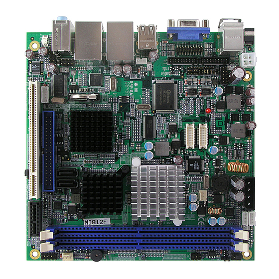
Page 17: Connector Locations On Mi812
INSTALLATIONS Connector Locations on MI812 MI812 User’s Manual... - Page 18 INSTALLATIONS MI812 User’s Manual...
-
Page 19: Fan1: Cpu Fan Power Connector
Remarks: CN1 and J3 cannot be connected at the same time. CN2: PS/2 Keyboard and PS/2 Mouse Connectors PS/2 Mouse PS/2 Keyboard Signal Name Keyboard Mouse Signal Name Keyboard data Mouse data N.C. N.C. Keyboard clock Mouse clock N.C. N.C. MI812 User’s Manual... -
Page 20: Cn3: Vga Connector
CN6: GbE RJ-45 and USB3/4 Ports CN7: Audio Connector CN8, CN9: Serial ATA Connectors CN10: Mini PCI- E(x1) Connector (bottom side) CN11: Compact Flash Connector (bottom side) PCI1: PCI Slot (supports 2 Master) PCIE_1: PCIE x1 Slot MI812 User’s Manual... -
Page 21: Ide1: Ide Connector
+12V Backlight Enable Backlight ADJ Ground Pin # Signal Name +12V Backlight ADJ Ground J2: HDD Power Connector (Output: Max. 2A) Pin # Signal Name +12V Ground Ground Note: +12V power is provided with 2A maximum load. MI812 User’s Manual... -
Page 22: J3: Atx_12V Connector
RXD, Receive data 5/15 TXD, Transmit data 7/17 DTR, Data terminal ready 9/19 Ground 2/12 DSR, Data set ready 4/14 RTS, Request to send 6/16 CTS, Clear to send 8/18 RI, Ring indicator 10/20 No Connect. *COM2 supports RS-232/422/485. MI812 User’s Manual... -
Page 23: J8, J10: Lvds Connectors (1St Channel, 2Nd Channel)
3/13 RXD, Receive data 5/15 TXD, Transmit data 7/17 DTR, Data terminal ready 9/19 Ground 2/12 DSR, Data set ready 4/14 RTS, Request to send 6/16 CTS, Clear to send 8/18 RI, Ring indicator 10/20 No Connect. MI812 User’s Manual... -
Page 24: J12: Wake On Lan Connector
Line2_R MIC2_ID Sense Line2_L Line2_ID J16: SPI Debug Tools Port (Factory use only) J17: Smart Battery Connector Pin # Signal Name PCIRST- EMTSMI- Ground SMBDATA SMBCLK J18: SPDIF Out Connector Pin # Signal Name SPDIF out Ground MI812 User’s Manual... -
Page 25: J19: Parallel Port
INSTALLATIONS J19: Parallel Port Signal Name Pin # Pin # Signal Name STB- BUSY SLCT AFD- ERR- INIT- SLIN- Ground Ground ACK- Protect Pin MI812 User’s Manual... - Page 26 INSTALLATIONS This page is intentionally left blank. MI812 User’s Manual...
-
Page 27: Bios Setup
BIOS SETUP BIOS Setup This chapter describes the different settings available in the Award BIOS that comes with the board. The topics covered in this chapter are as follows: BIOS Introduction ................24 BIOS Setup ..................24 Standard CMOS Setup ................ 26 Advanced BIOS Features .............. -
Page 28: Bios Introduction
The Award BIOS provides a Setup utility program for specifying the system configurations and settings. The BIOS ROM of the system stores the Setup utility. When you turn on the computer, the Award BIOS is immediately activated. Pressing the <Del> key immediately allows you to enter the Setup utility. - Page 29 Note: If the system cannot boot after making and saving system changes with Setup, the Award BIOS supports an override to the CMOS settings that resets your system to its default. Warning: It is strongly recommended that you avoid making any changes to the chipset defaults.
-
Page 30: Standard Cmos Setup
Sun to Sat Month : 1 to 12 Date : 1 to 31 Year : 1999 to 2099 To set the date, highlight the “Date” field and use the PageUp/ PageDown or +/- keys to set the current time. MI812 User’s Manual... - Page 31 You can choose the following video display cards: EGA/VGA For EGA, VGA, SEGA, SVGA or PGA monitor adapters. (default) CGA 40 Power up in 40 column mode. CGA 80 Power up in 80 column mode. MONO For Hercules or MDA adapters. MI812 User’s Manual...
- Page 32 Whenever the BIOS detects a non-fatal error, the system will stop and you will be prompted. All, But Keyboard The system boot will not be halted for a keyboard error; it will stop for all other errors MI812 User’s Manual...
-
Page 33: Advanced Bios Features
When the CPU requests data, the system transfers the requested data from the main DRAM into cache memory, for even faster access by the CPU. These items allow you to enable (speed up memory access) or disable the cache function. By default, these items are Enabled. MI812 User’s Manual... - Page 34 Settings are from 6 to 30 characters per second. Typematic Delay (Msec) When the typematic rate is enabled, this item allows you to set the time interval for displaying the first and second characters. By default, this item is set to 250msec. MI812 User’s Manual...
- Page 35 OS/2 that depends on certain BIOS calls to access memory. The default setting is Non-OS/2. Small Logo (EPA) Show The EPA logo appears at the right side of the monitor screen when the system is boot up. The default setting is Disabled. MI812 User’s Manual...
-
Page 36: Advanced Chipset Features
SDRAM. DRAM RAS# Precharge This option sets the number of cycles required for the RAS to accumulate its charge before the SDRAM refreshes. The default setting for the Active to Precharge Delay is Auto. MI812 User’s Manual... - Page 37 SDVO LVDS Protocol: 1Ch SPGW 18bit SDVO Panel Number: 640 x 480 Boot Display: CRT Panel Scaling: Auto Panel Number: 1024x768 18 bit SC Panel Scaling The default setting is Auto. The options available include On and Off. MI812 User’s Manual...
- Page 38 18bit SC 800x480 18bit SC 800x600 18bit SC 1024x768 18bit SC 1280x1024 18bit DC 1280x768 18bit SC 1280x800 18bit SC 1400x1050 18bit DC 1400x900 18bit DC 1600x1200 18bit DC 1920x1200 18bit DC 1366x768 18bit SC 1920x1080 18bit DC MI812 User’s Manual...
-
Page 39: Integrated Peripherals
Enter Hot Key power ON Ctrl-F1 Menu Level > Onboard Serial Port 1 3F8/IRQ4 Onboard Serial Port 2 2F8/IRQ3 Onboard Parallel Port 378/IRQ7 Parallel Port Mode EPP Mode Select EPP1.7 ECP Mode Use DMA PWRON After PWR-Fail MI812 User’s Manual... - Page 40 The fields under the SATA setting includes SATA Mode (IDE), On-Chip Serial ATA (Auto), PATA IDE Mode (Secondary) and SATA Port (PO, P2 is Primary). USB Controller The options for this field are Enabled and Disabled. By default, this field is set to Enabled. MI812 User’s Manual...
- Page 41 The default values for these ports are: Serial Port 1 3F8/IRQ4 Serial Port 2 2F8/IRQ3 Onboard Parallel These fields allow you to select the parallel ports and their addresses. The default values for these ports are: Parallel Port 378H/IRQ7 MI812 User’s Manual...
- Page 42 Extended Capabilities Port ECP+EPP Combination of ECP and EPP capabilities Normal Normal function PWRON After PWR-Fail This field sets the system power status whether on or off when power returns to the system from a power failure situation. MI812 User’s Manual...
-
Page 43: Power Management Setup
Min. Power Saving Minimum power management Max. Power Saving Maximum power management. User Define Each of the ranges is from 1 min. to 1hr. Except for HDD Power Down which ranges from 1 min. to 15 min. MI812 User’s Manual... - Page 44 By default, this field is disabled. Power On by Ring This field enables or disables the power on of the system through the modem connected to the serial port or LAN. USB KB Wakeup from S3 By default, this field is disabled. MI812 User’s Manual...
- Page 45 When an I/O device wants to gain the attention of the operating system, it signals this by causing an IRQ to occur. When the operating system is ready to respond to the request, it interrupts itself and performs the service. MI812 User’s Manual...
-
Page 46: Pnp/Pci Configurations
MPEG ISA/VESA VGA card. When this field is disabled, a PCI/VGA cannot work with an MPEG ISA/VESA card. Maximum Payload Size The default setting of the PCI Express Maximum Payload Size is 4096. MI812 User’s Manual... -
Page 47: Pc Health Status
PC health status. Smart Fan Temperature There are two smart fan functions available. When enabled, the user is allowed to set a threshold temperature which determines when the CPU/system fan would stop rotating. MI812 User’s Manual... -
Page 48: Frequency/Voltage Control
Spread Spectrum Modulated This field sets the value of the spread spectrum. The default setting is Disabled. This field is for CE testing use only CPU Host / SRC PCI Clock This field is set to Default. MI812 User’s Manual... -
Page 49: Load Fail-Safe Defaults
Select this option to exit the Setup utility without saving the changes you have made in this session. Typing “Y” will quit the Setup utility without saving the modifications. Typing “N” will return you to Setup utility. MI812 User’s Manual... - Page 50 BIOS SETUP This page is intentionally left blank. MI812 User’s Manual...
-
Page 51: Drivers Installation
Realtek High Definition Audio Driver Installation ......52 LAN Drivers Installation ..............54 IMPORTANT NOTE: After installing your Windows operating system (Windows 2000/ XP), you must install first the Intel Chipset Software Installation Utility before proceeding with the drivers installation. MI812 User’s Manual... -
Page 52: Intel Chipset Software Installation Utility
Plug & Play INF support for Intel chipset components. Follow the instructions below to complete the installation under Windows 2000/XP. 1. Insert the CD that comes with the board. Click Intel Chipsets and then Intel(R) I945GM/GME/GSE Chipset Drivers. 2. Click Intel(R) Chipset Software Installation Utility. MI812 User’s Manual... - Page 53 4. Click Yes to accept the software license agreement and proceed with the installation process. 5. In the Readme File Information window, click Next to continue to proceed with the installation process. 6. The utility setup is now complete. Click Finish to restart the computer. MI812 User’s Manual...
-
Page 54: Vga Drivers Installation
2. When the Welcome screen to the Setup Program appears, click Next to continue. 3. Click Yes to to agree with the license agreement and continue the installation process. 4. On Readme File Information screen, click Next to continue. MI812 User’s Manual... - Page 55 DRIVERS INSTALLATION 5. In the Setup Progress screen, click Next to continue the installation. 6. Setup is now complete. Click Finish to restart the computer. MI812 User’s Manual...
-
Page 56: Realtek High Definition Audio Driver Installation
3. When the Welcome to the InstallShield Wizard to Realtek High Definition Audio Driver screen appears, click Next to continue. 4. Setup has finished installing Realtek High Definition Audio Driver on your computer. Click Finish to restart the computer. MI812 User’s Manual... - Page 57 DRIVERS INSTALLATION MI812 User’s Manual...
-
Page 58: Lan Drivers Installation
Follow the steps below to install the Intel 82574L LAN Drivers. 1. Insert the CD that comes with the board. Click LAN Card and then Intel(R) PRO 82574L LAN Drivers. 2. In the next screen, click Install Drivers and Software. MI812 User’s Manual... - Page 59 5. In the Setup Options screen, click the checkbox of Drivers to select it and then click Next. 6. In the Ready to Install the Program screen, click Install to begin installation of the drivers. 7. When the InstallShield Wizard has been completed, click Finish. MI812 User’s Manual...
-
Page 60: Appendix
Parallel Port #1(LPT1) 360 - 36F Network Ports 3B0 - 3BF Monochrome & Printer adapter 3C0 - 3CF EGA adapter 3D0 - 3DF CGA adapter 3F0h - 3F7h Floppy Disk Controller 3F8h - 3FFh Serial Port #1(COM1) MI812 User’s Manual... -
Page 61: Interrupt Request Lines (Irq)
Serial Port #2 IRQ4 Serial Port #1 IRQ5 Reserved IRQ6 Floppy Disk Controller IRQ7 Parallel Port #1 IRQ8 Real Time Clock IRQ9 Reserved IRQ10 Reserved IRQ11 Reserved IRQ12 PS/2 Mouse IRQ13 80287 IRQ14 Primary IDE IRQ15 Secondary IDE MI812 User’s Manual... -
Page 62: Watchdog Timer Configuration
(argc != 2) printf(" Parameter incorrect!!\n"); return 1; if (Init_W627EHF() == 0) printf(" Winbond 83627HF is not detected, program abort.\n"); return 1; bTime = strtol (argv[1], endptr, 10); printf("System will reset after %d seconds\n", bTime); EnableWDT(bTime); return 0; //=========================================================================== MI812 User’s Manual... - Page 63 = Get_W627EHF_Reg( 0xF5); bBuf &= (!0x08); Set_W627EHF_Reg( 0xF5, bBuf); //count mode is second Set_W627EHF_Reg( 0xF6, interval); //set timer //=========================================================================== void DisableWDT(void) Set_W627EHF_LD(0x08); //switch to logic device 8 Set_W627EHF_Reg(0xF6, 0x00); //clear watchdog timer Set_W627EHF_Reg(0x30, 0x00); //watchdog disabled //=========================================================================== MI812 User’s Manual...
- Page 64 Init_Finish; W627EHF_BASE = 0x00; result = W627EHF_BASE; Init_Finish: return (result); //=========================================================================== void Unlock_W627EHF (void) outportb(W627EHF_INDEX_PORT, W627EHF_UNLOCK); outportb(W627EHF_INDEX_PORT, W627EHF_UNLOCK); //=========================================================================== void Lock_W627EHF (void) outportb(W627EHF_INDEX_PORT, W627EHF_LOCK); //=========================================================================== void Set_W627EHF_LD( unsigned char LD) Unlock_W627EHF(); outportb(W627EHF_INDEX_PORT, W627EHF_REG_LD); outportb(W627EHF_DATA_PORT, LD); Lock_W627EHF(); MI812 User’s Manual...
- Page 65 (W627EHF_BASE) #define W627EHF_DATA_PORT (W627EHF_BASE+1) //=========================================================================== #define W627EHF_REG_LD 0x07 //=========================================================================== #define W627EHF_UNLOCK 0x87 #define W627EHF_LOCK 0xAA //=========================================================================== unsigned int Init_W627EHF(void); void Set_W627EHF_LD( unsigned char); void Set_W627EHF_Reg( unsigned char, unsigned char); unsigned char Get_W627EHF_Reg( unsigned char); //=========================================================================== #endif //__W627EHF_H MI812 User’s Manual...
Need help?
Do you have a question about the MI812 and is the answer not in the manual?
Questions and answers