Table of Contents
Advertisement
Quick Links
Advertisement
Table of Contents

Related Manuals for Risco RP432KPTZ


Summary of Contents for Risco RP432KPTZ
- Page 1 RisControl Smart Home Gateway User Manual Model: RP432KPTZ/RP432KPTP...
-
Page 2: Table Of Contents
Contents INTRODUCTION ......................5 OPERATING THE RISCONTROL ..................6 Entering RisControl ...................... 6 The “RisControl Session” ....................8 RisControl Main Menu ....................8 RisControl Top Bar ....................... 9 Using Proximity Tags ....................10 Troubles Management ....................12 Communication troubles ................... 12 Confirm Troubles (Security Only mode) .............. - Page 3 Final Exit Zone ...................... 40 One Click Activation of all Partitions ..............40 Arming/Disarming Selected or All Partitions ............41 Groups ........................42 Detectors ........................43 Utility Outputs ......................45 SURVEILLANCE......................46 Cameras Screen ......................46 PIR CAM ........................47 Video Cameras ......................
- Page 4 Edit or Delete a User ..................... 67 Editing a User’s Own Details (performed by the User) ......... 68 Login to the RISCO Cloud ..................69 Date & Time ....................... 70 Date & Time Settings..................... 70 Maintenance Menu....................71 Walk Test ....................... 72 Siren Test .......................
-
Page 5: Introduction
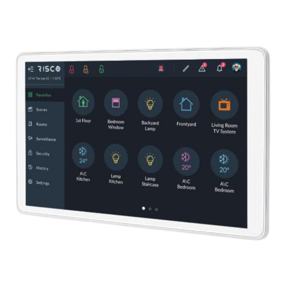
RisControl is a high-resolution Smart Touchscreen Keypad with an intuitive, easy to navigate user interface. RisControl combines standard keypad functionality with the ability to operate RISCO’s Smart Home cloud-based solution, and alarm and video, from one customizable screen. Figure 1: RisControl The RisControl can be used in 3 operation modes, as follows: •... -
Page 6: Operating The Riscontrol
OPERATING THE RISCONTROL Entering RisControl When not in use, the RisControl is in Screen Saver mode (see SCREEN SAVER, page 17). When the user clicks anywhere on the screen while the RisControl is in Screen Saver mode, the RisControl exits the mode and switches to the “Favorites Screen”. - Page 7 Figure 2b: RisControl Smart Home Only Opening Screen Figure 2c: RisControl Security Only Opening Screen...
-
Page 8: The "Riscontrol Session
The “RisControl Session” The “RisControl Session” is the duration of time after which the RisControl will return to the Screen Saver mode. It starts immediately after the Screen Saver screen is touched and opens, and it ends automatically following a predefined “idle” time (Session Timeout) during which the screen has not been touched. -
Page 9: Riscontrol Top Bar
Click to expand the menu Main menu Figure 4: Main Menu (collapsed mode) RisControl Top Bar The “RisControl Top Bar” appears at the top of numerous RisControl Screens with slight variations from screen to screen. Figure 5: Top Bar of the Opening Screen The End-User’s Avatar The End-User’s Avatar appears at the right side of the top bar of all the screens. -
Page 10: Using Proximity Tags
Figure 6: Manual Locking of the RisControl Session Arm/Partial Arm/Disarm buttons When clicked, these buttons will Arm, Partial Arm or Disarm all the partitions that are associated with the user that is currently logged in. Note: After clicking the Arm/Disarm button, you may be prompted to enter a PIN CODE or hold a Proximity Tag close to the proximity sensor on the RisControl. - Page 11 Proximity Card Reader Figure 7: RisControl Screen with Proximity Tag Reader...
-
Page 12: Troubles Management
Troubles Management Click the Trouble icon in the Top Bar of the RISCO Cloud to open a list of all the Troubles that exist in the system, as show in the example below. Note: The Trouble icon will appear only when there are Trouble messages. - Page 13 Figure 9: Communication Troubles Flow Troubles related to communication failure will be listed first, pinned to the top of the list. Click the “See Connection Status” button in the Troubles List; a popup is displayed, indicating the status of each of the connections. Figure 10: Communication Troubles Screen...
-
Page 14: Confirm Troubles (Security Only Mode)
Confirm Troubles (Security Only mode) Note: This section is applicable only to Grade-2 and Grade-3 installations. Users of lower grade installations can skip to the next section. Some of the troubles in Grade-2 and Grade-3 installations must be “confirmed” by the user. -
Page 15: Notifications Management
Notifications Management Click the Notifications icon in the Top Bar of the RisControl to open a list of all the notifications that are applicable to the RisControl, as shown in the example below. Note: The Notifications icon will appear only when there are Notification messages. Figure 12: Notification List Software Update Notification Whenever a Software Update is available, it will be pinned to the top of the... -
Page 16: Confirm Alarms
Confirm Alarms Note: This section is applicable only to Grade-2 and Grade-3 installations. Users of lower grade installations can skip to the next section. Some of the alarms in Grade-2 and Grade-3 installations must be “confirmed” by the user. In this case, the “Confirm all alarms” button will appear at the bottom of the alarm list. -
Page 17: Screen Saver
SCREEN SAVER The RisControl enters Screen Saver mode at the end of the session timeout in which the screen has not been touched. In this case, RisControl will display any one of a variety of screens as selected by the Grand Master (see page 62). Figure 14: Screen Saver Screen Exit/Entry Screen Saver Mode To exit the Screen Saver mode, simply touch the screen. - Page 18 Figure 15: Screen Saver during Alarm Screen Enter your PIN CODE or hold a Proximity Tag close to the proximity sensor on the RisControl to disarm the alarm.
-
Page 19: Favorites Screen
FAVORITES SCREEN The Favorites Screen allows you to set shortcuts to all frequently used or favorite activities in one screen, without having to navigate multiple screens to access them. Using the Favorites Screen When the user enters the RisControl, the Favorites Screen opens. Figure 16: Favorites Screen •... -
Page 20: Editing The Favorites Screen
Editing the Favorites Screen A user can edit the Favorites Screen. Click the pencil icon at the top of the screen to enter edit mode of the Favorites Screen. Figure 17: Favorites Screen – Edit Mode... -
Page 21: Adding Shortcut Buttons To The Favorites Screen
Adding Shortcut Buttons to the Favorites Screen The user can add shortcut buttons to the Favorites Screen. Note: A Favorites Screen that has at least one shortcut button will be the default screen that is displayed after exiting the screen saver. Click “+ Add new button”, the “Add Buttons to Favorites Screen”... -
Page 22: Removing Shortcut Buttons From The Favorites Screen
Adding Devices and Utility Outputs Buttons to the Favorites Screen Click the Devices side tab to open the list of devices and utility outputs. Click the bubble icons of the Utility Outputs that you wish to add to the Favorites Screen. Adding Scenes Buttons to the Favorites Screen All the displayed buttons will have a “V”... -
Page 23: Using The Shortcut Buttons From The Favorites Screen
Using the Shortcut Buttons from the Favorites Screen Using shortcut buttons from the Favorites Screen is similar to using the corresponding buttons in the Security and Cameras Screens (see SECURITY, page 38). Incoming Alarm on the Favorites Screen If an alarm is initiated in any of the partitions assigned to the RisControl, the alarm will appear as a floating button at the bottom right of the Favorites Screen, as shown below. - Page 24 Note: When the Floating Alarm button appears on the screen, the user can click on any of the buttons in the Favorites Screen except for the buttons that are covered by the floating alarm button.
-
Page 25: Scenes
SCENES The Scenes menu displays icons for rules that you manually activate and that were previously created from the Settings menu (see Manual Rule, page 80). Each new Scene (manual rule) is placed automatically in the Scenes screen. Note: You can delete Scenes only from the Settings menu. Figure 21: Scenes Screen... - Page 26 Changing the order of Scenes You can change the order of the Scenes icons on the screen. Click the pencil icon , as shown at the top of the previous screen. Figure 22: Changing the Order of the Scenes Screen Click and hold any of the icons on the screen and move them to a different position.
-
Page 27: Rooms
ROOMS Rooms are entities that are defined by the Installer via the RISCO Cloud. The Overview room is a fixed room and is always on the top left of the screen and includes all the Scenes and Smart Home devices that are defined in the system (the Overview room cannot be modified). - Page 28 2. Click a Room icon; a list is displayed of Scenes and Smart Home devices that are assigned to this room. Figure 24: Smart Home Devices Type Screen The devices of the selected room are displayed. The rooms containing the searched device name or part of the name will be displayed.
-
Page 29: Device Buttons Operations And Information
Device Buttons Operations and Information Operations Icon Operation* Basic function allows to operate the device with On/Off functionality using (COMMAND_CLASS_BASIC) Basic function allows you to open/close the Door using (COMMAND_CLASS_DOOR_LOCK) Figure 25: Door Lock Operation Screens... - Page 30 Icon Operation* Mode of operation: The mode selection will depend on the operation type of the door lock that is set by the installer as described in the table below: If you don’t see the timeout option then go to the cloud and change the operation type time in the cloud.
- Page 31 Icon Operation* Allows you to open/close the Door using (COMMAND_CLASS_BARRIER_OPERATOR) Long click on the icon: provides additional functionality and information. Figure 27: Garage Door Lock Function Screen Switch Binary function allows you to operate the device with On/Off functionality using (COMMAND_CLASS_SWITCH_BINARY) Figure 28: Switch Binary Function Screen...
- Page 32 Icon Operation* Switch Multilevel (Dimmer) / Roller Shutter: The Switch Multilevel / Roller Shutter function allows you to operate the device with dimming functionality using (COMMAND_CLASS_SWITCH_MULTILEVEL) and to set the Dimmer from 0%-100%. Roller Shutter (COMMAND_CLASS_SWITCH_MULTILEVEL) This function can also be used as a Roller Shutter. Figure 29: Switch Multilevel Screen Device last know value will move the Dimmer to the last nonzero value according to the device type.
- Page 33 Icon Operation* Thermostat: Allows you to change the Set point, Mode and Fan Mode using: (COMMAND_CLASS_THERMOSTAT_SETPOINT, COMMAND_CLASS_THERMOSTAT_MODE, COMMAND_CLASS_THERMOSTAT_FAN_MODE) Figure 31: Thermostat Function Screen • 25.4°C is the current Temperature of the sensor multilevel Temperature • 27°C is the Set point •...
-
Page 34: Information
Figure 32: Thermostat Setpoint Setting Screen Information Battery (COMMAND_CLASS_BATTERY) Long click: battery level will be accessible inside the device. Figure 33: Device Battery Level Screen Sensor Multilevel (COMMAND_CLASS_SENSOR_MULTILEVEL) Provides a list of sensors available on your device with their current value. Figure 34: List of Sensors on Device with Current Value Screen... - Page 35 Central Scene (COMMAND_CLASS_CENTRAL_SCENE) Provides information on Scene activation. Figure 35: Scene Activation Information Screen Notification (COMMAND_CLASS_NOTIFICATION) Provides a list of notifications and their last value. 1. Click the empty box shown in the screen below and then type the notification value in Hex (consult the device manual for the notification value).
- Page 36 Figure 37: Refresh Notification Screen Meter (COMMAND_CLASS_METER) Provides a list of meters supported by the device. Figure 38: Supported Meters by Device Screen...
- Page 37 Identification Indicator (COMMAND_CLASS_INDICATOR) Click the IDENTIFY button as shown in the screen below: the device will blink to identify itself. Figure 39: Device Identification Indicator Screen Note: If you use another controller to identify the RisControl, it will beep 5 times without blinking.
-
Page 38: Security
SECURITY The Security section of the RisControl describes all the operations and activities relevant to the Security System. An initiated alarm will appear as a floating button at the bottom right of the Security Screen (except for the Security→Partitions screen). Notes: 1. -
Page 39: Arming And Disarming
Stay=Orange Armed=Red Disarmed=Green Not ready=Gray Arming and Disarming The user can Full Arm, Stay Arm or Disarm any of the partitions on the screen. For example, if a user clicks a disarmed partition, a popup screen is displayed that allows the user to either Full Arm or Stay Arm the partition, as shown below. Figure 41: Arming a Partition Screen Note: A Partition that fails to arm is indicated as shown below. -
Page 40: Exit/Entry Delay
Exit/Entry Delay A partition that is defined with an Exit/Entry delay will indicate the remaining exit/entry time via a contour-line button. The time remaining will be displayed at the center of the button. In addition, a beeping sound will be emitted via the RisControl throughout the Exit/Entry time. -
Page 41: Arming/Disarming Selected Or All Partitions
Arming/Disarming Selected or All Partitions 1. Click “Select Partitions” at the top right of the screen to select one or more partitions. Figure 43: Selecting Multiple Partitions Screen Click to select the partitions to be Armed or Disarmed; a “√” is added to the partition icon –... -
Page 42: Groups
Groups A Group is a collection of zones from one or more partitions. The Security/Groups screen displays the groups that the user is associated with. A maximum of 4 groups can be defined in the system: A, B, C and D. Note: If the user is not associated to any group, the Security/Groups screen will be blank for the user. -
Page 43: Detectors
Figure 45: Selecting Groups Partitions Screen Select the required Partitions and then click the “Arm” button. The Group icon status indications (see above) also apply to the Group Partitions screen. Detectors The Security→Detectors screen lists all the devices that are part of the partitions that the user has permission to view. - Page 44 Figure 46: Security – Devices Screen There are three detector icon status indications, as follows: • Green: Disarmed • Red: Armed • Gray: Not Ready (zone is open) Click any of the detectors to either bypass the detector or if the detector is set to be a “Presence Zone”...
-
Page 45: Utility Outputs
Utility Outputs On the Utility Outputs Screen, click a Utility Output button to operate that output. • Gray: Output is Off • Green: Output is On Figure 48: Utility Outputs Screen... -
Page 46: Surveillance
The “Surveillance” section covers the following: • Video cameras that are connected directly to the RISCO Cloud • Video cameras that are connected to the RISCO Cloud through a RISCO Video Recorder • PIRCAMs that are connected through the RISCO Security System... -
Page 47: Pir Cam
• Video Camera through a Video Recorder Note: Connection through a Video Recorder is indicated by the red dot inside the camera icon. PIR CAM Click any of the PIR CAMs in the screen to view the images taken by that camera. Figure 50: PIR Camera Image View Click the “Take Photo”... -
Page 48: Video Cameras
The Cameras Screen displays cameras that are connected directly to the RISCO Cloud and cameras that are connected to the RISCO Cloud through a RISCO Video Recorder. Note: A camera that is connected via the RISCO Video Recorder is indicated by the red dot inside the camera icon. Direct Connection... -
Page 49: Quick Buttons
By clicking on a camera icon that is connected to a RISCO Video Recorder, the live view of the camera is displayed. These cameras can also switch to show pre- recorded video clips. An additional “Switch to Recording” button is displayed on the left side of the screen, as shown in the screen below. -
Page 50: Quick Buttons Tray
Figure 54: Quick Buttons Tray Quick Buttons Tray The Quick Buttons Tray allows the user to perform activities while viewing the image and or video clip. For example, where a living room is monitored by a video camera and the lighting in the living room is controlled via one of the Utility Outputs (UO) of the Security System. -
Page 51: Adding/Removing Quick Buttons From The Tray
Adding/Removing Quick Buttons from the Tray Upon entering the edit mode of the Quick Buttons Tray, all the Quick Buttons will appear with an “x” bubble on them. To remove the Quick Button from the tray, click the “x” bubble of the Quick Button. - Page 52 Figure 56: Editing the List of Quick Buttons 3. Select the “Apply to all” box to set the current selection of Quick Buttons to all the cameras.
-
Page 53: Video Recorder
When a video recorder is installed in a site, users can watch live videos and playback video clips from cameras that are connected via Surveillance. Note: The RisControl must be logged into the RISCO Cloud to be able to present playback from the Video Recorder. -
Page 54: Video Recorder Live Gallery
Video Recorder Live Gallery After you have logged into the RISCO Cloud, click the “VIDEO REC” tab: The Live Gallery screen is displayed. Figure 58: Video Rec Live Gallery Screen The Gallery displays a matrix of live videos taken from cameras, with the camera... -
Page 55: Camera Video Playback
Camera Video Playback To watch recorded video clips from any given camera, click the camera image in the Gallery, as shown in the example below. Figure 59: Playback Screen Time Slider The Time Slider that appears under an image, provides the exact time each video clip was recorded. -
Page 56: Playback Controls
Time Slider Center Pointer – the pointer at the center of the Time Slider is fixed, showing the exact time that it points to at each moment. Use your finger to slide the Time Slider left of right, until the Center Pointer points to the exact required time. -
Page 57: Switch Back To Live
Switch back to Live Click the “Switch to Live” button at any time to switch the view from Playback to Live camera mode. -
Page 58: History
HISTORY The History menu displays the History Screen, as shown in the example below. This screen is used for viewing a history log of events. For each event you can view the date and time that the event occurred, a description of the event and the detector or device that caused the event. -
Page 59: Media Events And Video Activities
Select a category to filter the search according to specific types of events Media Events and Video Activities You can view captured snapshot images or video clips recorded during specific related alarm events. Click the “Media Events” or “Video Activities” option, search for the event and then click on the event to view. -
Page 60: Settings
SETTINGS The Settings Menu displays the System Settings Screen, as shown in the example below. This screen is used for defining RisControl parameters and date and time settings. After entering “Settings”, and when the installation includes a Security Panel, the user is prompted to enter their PIN Code or hold a Proximity Tag close to the proximity sensor on the RisControl. -
Page 61: General
The RisControl will search for available networks and allow the user to select one of them. Note: RisControl can be used without connection to the RISCO Cloud. In this case, most operations that are applicable to the Security System will be available, except for Cameras, Video Recorders and other cloud related features that are not supported. -
Page 62: Session Timeout
Session Timeout The RisControl automatically displays the screen saver after a predefined time (Session Timeout) during which the screen has not been touched. The Grand Master can select between a 15, 30 or 40-second session timeout. Click the Session Timeout option in the menu. Select the preferred duration. -
Page 63: Language
Manual (software) update is performed by the Grand Master and is applicable only to a RisControl that is connected to the Internet through the Wi-Fi network. Click the “Check for Update” button; if an update is available, the following RISCO Cloud screen is displayed. - Page 64 Figure 68: Software Update Screen Click the “Update Now” button; a download of the updated software version is initiated. Note: The downloaded version is not installed automatically but must be initiated by the Grand Master. If a search for updates by the Grand Master shows an update to be downloaded, the following Software Update menu option is displayed.
-
Page 65: Users And Permission Settings
The Grand Master and Master Users can add users to the Security System from the RisControl. Note: The "Add User" procedure in the RisControl refers to adding Panel Users and not Cloud Users which is a separate procedure performed using the RISCO Web User Application. Figure 70: Users List Screen... -
Page 66: Add A User
Proximity Tag Assign a Proximity Tag for the New User - one that is not assigned to another RISCO Cloud user Û A Proximity Tag can be assigned to one RISCO Cloud user only... -
Page 67: Edit Or Delete A User
User Settings Description Icon Select an avatar that will represent the user Click the “Add User” button to complete the procedure; a success message will be displayed confirming that the new user is now valid and operational. Notes: A User must be assigned either a PIN Code, a Proximity Tag or both. The “Add User”... -
Page 68: Editing A User's Own Details (Performed By The User)
Click on your own username; the following screen is displayed. Figure 73: Edit User’s Own Details Screen You can modify the details of the user, such as name, assigned partitions, PIN Code, Icon. You can also delete the user from the RISCO Cloud Account. -
Page 69: Login To The Risco Cloud
Enter your RISCO Cloud credentials in the corresponding fields. Click the “Login” button. Note: By entering your RISCO Cloud credentials you will direct this specific RisControl to always present to all its users the cameras and video recordings that are assigned to that... -
Page 70: Date & Time
Date & Time Enter the Settings Menu and select Date & Time to display the Date & Time Screen, as shown below. This screen is used for defining date and time settings for the RisControl. Figure 75: Date &Time Screen Date &... -
Page 71: Maintenance Menu
Maintenance Menu Enter the Settings Menu and select “Maintenance”. Figure 76: Maintenance Screen The Grand Master can perform the following maintenance activities: • Walk Test • Siren Test • Service Mode • Restart Keypad • Upload Logs File • Anti Code •... -
Page 72: Walk Test
Walk Test In the “Walk Test” option, click the “CHECK” button; the Walk Test begins. 2. Trip the zones to be tested; the results will be displayed on the screen, as in the example below. Figure 77: Walk Test Result Screen The duration for the “Walk Test”... -
Page 73: Siren Test
Siren Test Click the “CHECK” button to enter the “Siren Test”. Figure 78: Siren Test Screen Click the “Siren Test” or the “Strobe Test” button to perform the test. Service Mode Activating “Service” mode silences all tamper alarms from detectors and accessories for an installer-defined duration of time. -
Page 74: Upload Logs File
Upload Logs File You can upload log files to a predefined storage location, where access to these files will be given to RISCO support. Click the “Upload Logs File” button; the file name will be displayed on the next screen that opens. -
Page 75: Monitoring Station
Figure 80: Entering an Anti-Code Screen The “Panel Code” is generated automatically by the Security System Contact the installer and inform him of the Panel Code. The Installer uses the Panel Code to generate the “Anti-Code”. Contact the installer and inform him of the Anti-Code. Enter the code in the “Anti-Code”... -
Page 76: Sounds
Sounds The user can change the sound settings of the RisControl. The user can also individually turn on/off the following sounds: • Buzzer • Key tones • Chime Click “Sounds” in the Settings Menu; the following screen is displayed. Figure 81: Sound Settings Screen Drag to set the volume of the RisControl speaker (also increases/decreases all the sounds that are generated by the RisControl). -
Page 77: Follow Me
Follow Me The user can add Follow Me recipients, up to the limit defined in the panel. Adding a Follow Me Recipient Click the “Follow Me” option of the Maintenance and click the “+” button at the top bar. Figure 82: Follow Me Screen The following screen is displayed. -
Page 78: Test Or Edit A Follow Me
To edit or send a test message, click the “Test” or “Edit” button in the Follow Me List. Service Info Click Service info to view the contact details of the installation company defined in the control panel or iRISCO app (if the RisControl is connected to the RISCO Cloud). Figure 84: Service Info Screen... -
Page 79: Rules
RULES Rules allow you to operate a pre-set sequence of alarm commands and smart home devices. Rules can be triggered by manually pressing a button, by a daily, weekly or monthly schedule or by system events. There are three types of rules, as follows: •... -
Page 80: Manual Rule
Manual Rule Figure 86: Add New Rule Settings Screen In the “Name field”, enter a suitable name for the rule. Under “Trigger”, select Manual. Under “Rooms” click the arrow and select the group to which to apply the rule. Under “Icon” select an icon and then select a color for the icon from the displayed colors;... -
Page 81: Schedule Rule
Schedule Rule Figure 87: Schedule Rule Screen In the “Name field”, enter a suitable name for the rule. Under “Trigger”, select Schedule. Rule Active defines the duration of time during which the rule will be active. Select the Rule Active duration of time: •... - Page 82 Figure 88: Schedule Trigger Main Screen Schedule Trigger allows you to activate the rule at a specific time and day and at recurring daily, weekly or monthly duration of times. The following section is divided into: • Daily Schedule • Weekly Schedule •...
- Page 83 Daily Schedule The daily schedule allows the rule to be activated at a start time every “x” number of days, as defined. Figure 89: Defining Daily Schedule Screen Select Daily Under “Rule start time”, click the drop-down list and select one of the following options and then enter the rule start time in the provided field.
- Page 84 IMPORTANT! The sunrise/sunset rule start time will be available only if the RisControl is connected to the RISCO Cloud, and the site address is properly configured in the RISCO Cloud. Figure 90: Rule Trigger Start Time Screen Note: Sunrise and sunset times will be set according to the site location defined by the installer.
- Page 85 Weekly Schedule The weekly schedule allows the rule to be activated at a start time on specific days of the week. Figure 91: Defining Weekly Schedule Screen Select Weekly. Under “Rule start time”, click the drop-down list and select one of the available options and then enter the rule start time in the provided field.
- Page 86 Monthly Schedule The monthly schedule allows the rule to be activated at a start time and date every “x” number of months, as defined. Figure 92: Defining Monthly Schedule Screen Select Monthly. Under “Rule start time”, click the drop-down list and select one of the available options and then enter the rule start time in the provided field.
-
Page 87: Event Rule
Event Rule Figure 93: Event Rule Screen In the “Name field”, enter a suitable name for the rule Under “Trigger”, select Event. Rule Active defines the duration of time during which the rule will be active. Select the Rule Active duration of time: •... - Page 88 Figure 94: Event Rule Trigger Screen Select to activate the rule when: an alarm system event occurs; upon detection event when alarm is disarmed; or when a smart device changes status. Under “Rule Works”, click the drop-down list and select one of the available options: •...
- Page 89 Figure 95: Alarm System Event Selection Screen Select an alarm/disarm for the event and then click the “ADD PARTITION” button. Figure 96: Alarm System Event Partition Selection Screen 10. Select a partition to assign to the event and then Click “Next”. Go to Performing Actions to continue (page 90).
-
Page 90: Performing Actions
Performing Actions Actions allow you to automatically arm/disarm selected partitions in different modes. You can also activate smart home devices and utility outputs. In addition, the time sequence of actions can be delayed from one action to the next. To Arm/Disarm Figure 97: Add New Rule –... - Page 91 Select between Arm, Partial Arm, Group and Disarm. Select the Delayed Action checkbox to delay the action and then enter the delay time in the provided field. Select from the available partitions. If Group Arm was selected, also select the Groups (A—D) to be armed per partition.
- Page 92 To activate smart home devices: Figure 100: Actions –Automation Screen From the opening Actions screen, Select “+ Automation”. Figure 101: Actions – Automation Select Device Screen Click the All Rooms arrow and select the Room/Rooms to apply the smart device activation.
- Page 93 Select the Delayed Action checkbox to delay the smart device activation and then enter the delay time in the provided field. Select one of the available devices and then click “Next”. Figure 102: Actions – Automation Device Screen Activate/deactivate the device. Figure 103: Actions –...
-
Page 94: View Rules Summary
View Rules Summary You can view a summary of the rules settings before saving the rule. Note: The Summary screen varies according to Manual / Schedule / Event Trigger. Click the “4.SUMMARY” tab; the following screen is displayed. Figure 104: Actions Summary Screen If the viewed information is correct;... -
Page 95: Set Night Mode
Set Night Mode Night Mode is used when the activation of a device follows the triggering of an event condition only during nighttime. For example, switching on a light switch during the night. You can set specific time parameters to designate Night Mode. From the Rules screen above , click the “Set Night Mode”... - Page 96 To Set Night Mode according to specific times: Click “At’; the following time frame screen opens: Figure 106: Set Time Screen Set the time for the start/end of Night Mode (from 00:00 to 23:59). Click the “OK” button. To Set Night Mode before/after Sunset/Sunrise: Click the dropdown list and select either Before Sunrise, After Sunrise, Before Sunset or After Sunset.
- Page 97 Figure 108: Set Night Start Time and End Time Screen Click the “SAVE” button.
-
Page 98: Set Vacation
Set Vacation A vacation is a period of time during which all rules that were set to operate during vacations will be active, and rules that were set not to operate during vacations will be inactive. From the Rules screen above, click the “Set Vacation” button; the following screen is displayed. - Page 99 Select the vacation end date and then set the vacation end time Select the “Yearly Recurring Vacation” checkbox to automatically schedule the same times and dates entered in future years. Note: The last date on the screen indicates the end date and dates in between the start and end dates are enclosed in open-ended rectangles –...
-
Page 100: Emergency
EMERGENCY The Emergency button appears at the top of the screen. Note: The Emergency button will appear on the screen only if Emergency Keys was enabled by the installer in the panel. Figure 112: Emergency Button Screen Activating the Emergency Click the Emergency button ;... - Page 101 Figure 114: Click both buttons simultaneously To activate the Emergency call, click the corresponding two buttons simultaneously for at least 2 seconds.
-
Page 102: Specifications
SPECIFICATIONS Operating Voltage 13.8V ±10% Power consumption 170 mA, 5W max. Display 8-inch IPS, Resolution 800x1280, Illumination 300 cd/m Type of touch screen Capacitive touch, 5-point touch control supported System Android 7.1.2 A83T Octa-core Cortex A7 Memory 1G DDR3M RAM, 8G EMMC Flash Wi-Fi 802.11 b/g/n 2.4 GHz Bluetooth... -
Page 103: Ukca And Ce Red Compliance Statement
UKCA and CE RED Compliance Statement: Hereby, RISCO Group declares that this equipment is in compliance with the essential requirements of the UKCA Radio Equipment Regulations 2017 and CE Directive 2014/53/EU. For the UKCA and CE Declaration of Conformity please refer to our website: www.riscogroup.com... - Page 104 RISCO, for a period of (i) 24 months from the date of delivery of the Product (the “Warranty Period”). This Limited Warranty covers the Product only within the country where the Product was originally purchased and only covers Products purchased as new.
- Page 105 WARRANTY APPLICABLE THERETO, IF ANY, IS THE BATTERY MANUFACTURER'S WARRANTY. RISCO does not install or integrate the Product in the end user’s security system and is therefore not responsible for and cannot guarantee the performance of the end user’s security system which uses the Product or which the Product is a component of.
-
Page 106: Important Notice
RISCO Group. The information contained herein is for the purpose of illustration and reference only. -
Page 107: Contacting Risco Group
Compliant with Z-Wave Plus ® © RISCO Group 2024. All rights reserved. No part of this document may be reproduced in any form without prior written permission from the publisher. 11/2024...
Need help?
Do you have a question about the RP432KPTZ and is the answer not in the manual?
Questions and answers