Advertisement
Quick Links
SKU:DFR0654 (https://www.dfrobot.com/product-2195.html)
(https://www.dfrobot.com/product-2195.html)
1. Introduction
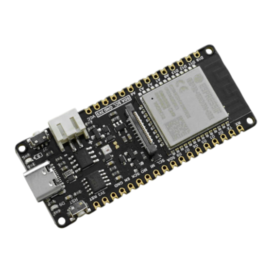
FireBeetle ESP32-E, specially designed for IoT, is an ESP-WROOM-32E-based main controller board with dual-core chips. It supports WiFi and
Bluetooth dual-mode communication, and features small size, ultra-low power consumption, on-board charging circuit and easy-to-use
interface, which can be conveniently used for smart home IoT, industrial IOT applications, wearable devices and so on. You can easily create your
own IoT smart home system when connecting it with an IoT platform like IFTTT. FireBeetle ESP32-E supports Arduino programming, and will
support Scratch graphical programming and MicroPython programming very soon. We provide you with detailed online tutorials and
application cases, and there are thousands of sensors with welding-free Gravity interface and actuators to help you get started easily. Besides,
th
t
h l d i
k
it bl t b
il
b dd d i
PCB
tl
i
t
d ti
t b ild
d t t
t t
Advertisement

Subscribe to Our Youtube Channel
Related Manuals for DFRobot FireBeetle ESP32-E


Summary of Contents for DFRobot FireBeetle ESP32-E
- Page 1 IoT, industrial IOT applications, wearable devices and so on. You can easily create your own IoT smart home system when connecting it with an IoT platform like IFTTT. FireBeetle ESP32-E supports Arduino programming, and will support Scratch graphical programming and MicroPython programming very soon.
- Page 2 Turn your worthy ideas into fantastic reality with this FireBeetle board! 3. Features Compatible with DFRobot FireBeetle V2 Series Small Size of 25.4×60 mm ESP32 Dual-core low power maincontroller, WiFi+BT4.0 GDI Display Port, esay to connect Onboard Charging Circuit and PH2.0 li-ion Battery Interface...
- Page 3 Max Charge Current: 500mA Support USB Charging Processor: Tensilica LX6 dual-core processor (One for high-speed connection; one for independent application development) Main Frequency: 240MHz SRAM: 520KB Flash: 32Mbit Wi-Fi Standard: FCC/CE/TELEC/KCC Wi-Fi Protocol: 802.11 b/g/n/d/e/i/k/r (802.11n,speed up to 150 Mbps), A-MPDU and A-MSDU Aggregation, support 0.4us guard interval) Frequency Range: 2.4~2.5 GHz Bluetooth Protocol: Bluetooth v4.2 BR/EDR and BLE standard compliant Bluetooth Audio: CVSD and SBC audio...
- Page 4 5. Board Overview...
- Page 5 13 μA after controlling the maincontroller enter the sleep mode through the program. Note: when the pad is disconnected, you can only drive RGB LED light via the USB Power supply. GDI Display Interface: DFRobot dedicated display interface, details will be given later. ESP32 Module: the newest ESP32-e module launched by ESPRESSIF Button: control the button via pin 27/D4 6.
- Page 6 Overview FireBeetle ESP32-E has up to 22 physical GPIOs, of which the pins 34-39 are only used as input pins, and others can be used as both input and output pins. All logic voltages are 3.3V. Control: FireBeetle Enable/reset pin...
- Page 7 Port Pin: the default physical pin number of the chip, which can be directly used to control the corresponding pin IDE: In Arduino IDE, the pin numbers have been remapped by FireBeetle, or you can directly use this symbol to control the corresponding RTC PIN: FireBeetle supports low power function, and in deepsleep mode, only RTC pins can be used.
- Page 8 UART ESP32 has two UART ports, of which UART0 is for PC communication. SerialPort Name Arduino UART0 Serial Pin1 Pin3 UART2 Serial2 Pin17 Pin16 7. Getting Started (Use for first time) 7.1 Arduino IDE Configuration When using FireBeetle maincontroller for the frist time, you need know the following steps: Add the json link in IDE Download the core of the maincontroller Select development board and serial port...
- Page 9 Click the icon marked with red below.
- Page 11 Copy the address to the newly popped up box: http://download.dfrobot.top/FireBeetle/package_DFRobot_index.json (http://download.dfrobot.top/FireBeetle/package_DFRobot_index.json) Click OK. Update board. Open Tools->Board->Boards Manager.
- Page 12 The board will be automatically updated.
- Page 13 Wait for while, then you will find the FireBeetle-ESP32(V0.0.8 Available now) in the list. Click "Install":...
- Page 14 Done! You can find the installed FireBeetle-ESP32 board in the list now.
- Page 15 7.2 Blink This is a blink program for users who use Arduino for the first time. The LED will blink regularly when burning codes into your board. The default blink LED for FireBeetle-ESP32 board is D9/2. Select Board and Port Click Tools>Board;...
- Page 16 Click Tools>Board; Select FireBeetle-ESP32-E Click port to select the corresponding port Programming...
- Page 17 // the setup function runs once when you press reset or power the board void setup() { // initialize digital pin LED_BUILTIN as an output. pinMode(LED_BUILTIN, OUTPUT); // the loop function runs over and over again forever void loop() { digitalWrite(LED_BUILTIN, HIGH);...
- Page 18 7.3 Bluetooth Tutorial The ESP32 supports Bluetooth function. This part will mainly demonstrate how to use two FireBeetle-ESP32-E for realizing Bluetooth Data Transparent Transmission.
- Page 19 //This example code is in the Public Domain (or CC0 licensed, at your option.) //By Victor Tchistiak - 2019 //This example demostrates master mode bluetooth connection and pin //it creates a bridge between Serial and Classical Bluetooth (SPP) //this is an extention of the SerialToSerialBT example by Evandro Copercini - 2018 #include "BluetoothSerial.h"...
- Page 20 if(connected) { Serial.println("Connected Succesfully!"); } else { while(!SerialBT.connected(10000)) { Serial.println("Failed to connect. Make sure remote device is available and in range, then restart app."); // disconnect() may take upto 10 secs max if (SerialBT.disconnect()) { Serial.println("Disconnected Succesfully!"); // this would reconnect to the name(will use address, if resolved) or address used with connect(name/address). SerialBT.connect();...
- Page 21 //This example code is in the Public Domain (or CC0 licensed, at your option.) //By Evandro Copercini - 2018 //This example creates a bridge between Serial and Classical Bluetooth (SPP) //and also demonstrate that SerialBT have the same functionalities of a normal Serial #include "BluetoothSerial.h"...
- Page 22 Result...
- Page 23 Send "I'm the master" from the mater port. The slave port displays "The slave receives: I'm the master" Send "I'm the slave" from the slave port. The master port displays "The master receives: I'm the slave".
- Page 24 Member Functions SerialBT.begin() Description:init Bluetooth module SerialBT.disconnect() Description: disconnect device Return: ture/false SerialBT.connect() Description: connect device Return: ture/false SerialBT.available() Description: judge if the Bluetooth received data SerialBT.read() Description: read the information received by the Bluetooth Return: string SerialBT.write() Description: send message by Bluetooth 7.4 WiFi Tutorial The ESP32 supports WiFi function.
- Page 25 WiFiAccessPoint.ino Create a wifi hotspot, and provide a web service Steps: 1. Connect to the wifi "yourAp" 2. Visit http://192.168.4.1/H to turn on the LED; Visit http://192.168.4.1/L to turn off the LED Run raw TCP "GET /H" and "GET /L" on PuTTY terminal with 192.168.4.1 as IP address and 80 as port #include <WiFi.h>...
- Page 26 Serial.println(myIP); server.begin(); Serial.println("Server started"); void loop() { WiFiClient client = server.available(); // listen for incoming clients if (client) { // if you get a client, Serial.println("New Client."); // print a message out the serial port String currentLine = ""; // make a String to hold incoming data from the client while (client.connected()) { // loop while the client's connected if (client.available()) {...
- Page 27 } else if (c != '\r') { // if you got anything else but a carriage return character, currentLine += c; // add it to the end of the currentLine // Check to see if the client request was "GET /H" or "GET /L": if (currentLine.endsWith("GET /H")) { digitalWrite(LED_BUILTIN, HIGH);...
- Page 28 Use the browser to access the IP address, then you will get the result as shown in the figure below Click to turn the LED on/off.
- Page 29 Member Functions begin() Description: Init WiFi module softAP(ssid,password) Description: Configure WiFi to AP mode, and set name and password Parameter: ssid: WiFi name in AP mode password: WiFi password in AP mode disconnect() Description:disconnect client connect() Description: connect client read() Description: Read the data received by WiFi write()
- Page 30 void setup() Serial.begin(9600); void loop() Serial.printf("hallRead:%d\n",hallRead()); delay(200); Result...
- Page 31 Member Function hallRead() Description: read the value of built-in hall sensor Return: return integer 0-255; Positive number for North pole; Negative number for South pole. The stronger the magnetic field, the greater the absolute value 7.5 Compacitive Keys ESP32 provides the function of capacitive touch sensor. There are 9 touch sensors (T0, T2 ~ T9)available, corresponding to pins 4, 2, 15, 13, 12, 14, 27, 33 and 32 respectively.
- Page 32 Member Functions TouchRead(pin) Description: no need to set PinMode Parameter: pin: touch sensor pin to be called Return*: range 0~255. The stronger the touch force, the greater the return value.
- Page 33 7.6 GDI This is a DFRobot special GDI display interface. It can be conveniently connected to a screen with 18pin-FPC cable, easy to get started. The pin list for GDI: FPC PINS FireBeetle M0 PINS Description 3.3V...
- Page 34 BLK(PWM adjustment) 12/D13 Backlit FPC PINS FireBeetle M0 PINS Description SCLK 18/SCK SPI clock MOSI 23/MOSI Master output, slave input MISO 19/MISO Master input, slave output 25/D2 Data/command 26/D3 Reset 14/D6 TFT chip select SDCS 13/D7 SD card chip select 0/D5 Font library 4/D12...
- Page 35 GDI supported screen: 1. 1.54inch 240x240 IPS TFT LCD Display with MicroSD Card Breakout (https://www.dfrobot.com/product-2072.html) 2. 2.0inch 0x240 IPS TFT LCD Display with MicroSD Card Breakout (https://www.dfrobot.com/product-2071.html) 3. 2.8inch 320x240 IPS TFT LCD Touchscreen with MicroSD (https://www.dfrobot.com/product-2106.html) 4.
- Page 36 #include <FastLED.h> // How many leds in your strip? #define NUM_LEDS 1 // For led chips like WS2812, which have a data line, ground, and power, you just // need to define DATA_PIN. For led chipsets that are SPI based (four wires - data, clock, // ground, and power), like the LPD8806 define both DATA_PIN and CLOCK_PIN // Clock pin only needed for SPI based chipsets when not using hardware SPI #define DATA_PIN 5...
- Page 37 leds[0] = CRGB::Blue; FastLED.show(); delay(500); Member Functions leds[0] = CRGB::Red Description: set the LED No.0 to red FastLED.show() Description: light up or change LED color leds[0].r = 255 Description: Set the R value of the first LED on the LED strip to 255 leds[0].g = 125 Description: Set the G value of the first LED on the LED strip to 125 leds[0].b = 0...
- Page 38 #define uS_TO_S_FACTOR 1000000ULL /* Conversion factor for micro seconds to seconds */ #define TIME_TO_SLEEP /* Time ESP32 will go to sleep (in seconds) */ RTC_DATA_ATTR int bootCount = 0; Method to print the reason by which ESP32 has been awaken from sleep void print_wakeup_reason(){ esp_sleep_wakeup_cause_t wakeup_reason;...
- Page 39 Serial.println( Boot number: + String(bootCount)); //Print the wakeup reason for ESP32 print_wakeup_reason(); First we configure the wake up source We set our ESP32 to wake up every 5 seconds esp_sleep_enable_timer_wakeup(TIME_TO_SLEEP * uS_TO_S_FACTOR); Serial.println("Setup ESP32 to sleep for every " + String(TIME_TO_SLEEP) + "...
- Page 40 void loop(){ //This is not going to be called Member Functions esp_sleep_get_wakeup_cause() Descriptin:Check which wake-up source triggered a wake-up from sleep mode esp_deep_sleep_start() Descriptin:Enter sleep mode esp_sleep_enable_timer_wakeup(TIME_TO_SLEEP * uS_TO_S_FACTOR) Descriptin:user timer to start wake-up from deep sleep. 8. Arduino Tutorial Basics 8.1 GPIO Digital IO digitalRead(pin)
- Page 41 pin:the Arduino pin number. value:HIGH or LOW. pinMode(pin, mode) Description: Configures the specified pin to behave either as an input or an output Parameter: pin:the Arduino pin number to set the mode of. mode:INPUT, OUTPUT, or INPUT_PULLUP. Control LED via Keys Analog IO AnalogRead(pin)...
- Page 42 Parameter: pin:the Arduino pin to write to. Allowed data types: int. value:the duty cycle: between 0 (always off) and 255 (always on). Allowed data types: int. 8.2 Serial Serial.begin(speed) Description: Sets the data rate in bits per second (baud) for serial data transmission. For communicating with Serial Monitor, make sure to use one of the baud rates listed in the menu at the bottom right corner of its screen.
- Page 43 Software Serial SoftwareSerial() Running time Function micros() Description: Returns the number of microseconds since the Arduino board began running the current program. millis() Description: Returns the number of milliseconds passed since the Arduino board began running the current program. Delay Functions delay(ms)...
- Page 44 duration:the duration of the tone in milliseconds (optional). Allowed data types: unsigned long. noTone(pin) Description: Stops the generation of a square wave triggered by tone(). Has no effect if no tone is being generated. Parameter: pin:the Arduino pin on which to stop generating the tone frequency:the frequency of the tone in hertz.
- Page 45 Description: Re-enables interrupts (after they’ve been disabled by noInterrupts(). Interrupts allow certain important tasks to happen in the background and are enabled by default. Some functions will not work while interrupts are disabled, and incoming communication may be ignored. Interrupts can slightly disrupt the timing of code, however, and may be disabled for particularly critical sections of code.。 noInterrupts()...
- Page 46 Description: Get the number of bytes (characters) of the received value Parameter: write:() Description: When it is in host state, the host will add the data to be sent to the sending queue; when it is in the slave state, the slave will send the data to the requesting host.
- Page 47 stop:boolean. true will send a stop message, releasing the bus after transmission. false will send a restart, keeping the IIC connection active. onReceive() Description: 8. onReceive() Function: Registers an event to be triggered when a slave device receives a transmission from a master. Grammar: Wire.onReceive(handler)...
- Page 48 MOSI pins will be pulled down and the SS pin will be pulled up. end() Description: turn off SPI BUS communication setBitOrder() Description: Set transmission order setBitOrder() Description: Set communication clock. The clock signal is generated by the master, and the slave is not configured. But the SPI clock frequency of the master should be within the processing speed range allowed by the slave.
- Page 49 open() Description: Opens a file on the SD card. If the file is opened for writing, it will be created if it doesn't already exist (but the directory containing it must already exist). Grammar: SD.open( filename) SD.open(filename,mode) Parameter: filename: the name the file to open, which can include directories (delimited by forward slashes, /) - char * mode (optional): the mode in which to open the file, defaults to FILE_READ - byte.
- Page 50 filename: the name of the directory to remove, with sub-directories separated by forward-slashes, / Return*: booleantype. True if the removal of the directory succeeded, false if not. File Class The file class provides the function of reading / writing files. The function of this class is very similar to the that of serial port related functions used before.
- Page 51 peek() Description: Read a byte from the file without advancing to the next one. Parameter: file: an instance of the File class Return*: The next byte (or character), or -1 if none is available. position( ) Description: Get the current position within the file (i.e. the location to which the next byte will be read from or written to). Syntax: file. position() Parameter: file: an instance of the File class...
- Page 52 BASE (optional): the base in which to print numbers: BIN for binary (base 2), DEC for decimal (base 10), OCT for octal (base 8), HEX for hexadecimal (base 16). seek() Description: Seek to a new position in the file, which must be between 0 and the size of the file (inclusive). Syntax: file. seek( pos) Parameter: file:an instance of the File class pos: the position to which to seek...
- Page 53 data:the byte, char, or string (char*) to write buf: an array of characters or bytes len:the number of elements in buf Return*: the number of bytes written isDirectory() Description: Reports if the current file is a directory or not Syntax: file.isDirectory() Parameter: file: an instance of the File class Return*:boolean.
- Page 54 IRrecv class can be used to receive and decode infrared signals. Before using this class, you need to instantiate an object of the class. Its member functions are as follows. IRrecv() Description: construct function of IRrecv class. Specify the pin the IR receiver connects to on Arduino. Syntax: IRrecvobject(recvpin) Parameter: object: user-defined object name recvpin: Arduino pin connect to IR receiver...
- Page 55 IRsend class The IRsend class can encode and send infrared signals. IRsend(object) Description: Construct function of IRsend class Parameter: object: an object of IRsend class sendNEC() Description: Sends the specified value in NEC encoded format. Syntax: IRsend.sendNEC(data,nbits) Parameter: IRsend: an object of IRsend class. data: encode value to send nbits: number of encodeing bits sendSony()...
- Page 56 9.3 WIFI ESP32 supports WiFi connection of both STA and AP mode. STA mode: ESP32 module connects Internet through router, and mobile phone or computer realizes remote control of equipment through Internet. AP mode: ESP32 module acts as a hot spot to enable the communicate between the module and mobile phone/computer, and realize the wireless LAN controlling.
- Page 57 #include <WiFi.h> #include <HTTPClient.h> #include <ArduinoJson.h> HTTPClient http; const char* ssid="dfrobotOffice"; const char* password="dfrobot2011"; const char* ntpServer = "pool.ntp.org"; const long gmtOffset_sec = 28800; const int daylightOffset_sec = 0; DynamicJsonDocument doc(1024); DynamicJsonDocument doc1(1024); void printLocalTime(){ struct tm timeinfo; if(!getLocalTime(&timeinfo)){ Serial.println("Failed to obtian time"); return ;...
- Page 58 JsonObject obj1 = doc1.as<JsonObject>(); String city = obj1["city"]; String temp1 = obj1["temp1"]; String temp2 = obj1["temp2"]; String weather = obj1["weather"]; String cityInfo ="Address:"+ city; String tempInfo =" Temperature: " + temp1 + "~" + temp2; String cityWeatherinfo = " Weather: " + weather; Serial.println("The weather conditions obtained are as follows: ");...
- Page 59 Serial.println("WiFi Disconnect"); Description: This demo shows how to obtain the network time through WiFi function and get the weather by visiting the http://www.weather.com.cn/datalcityinfo/101010100.html (http://www.weather.com.cn/datalcityinfo/101010100.html) . "101010100" in this interface is the city code. Note: you need to download arduino json library in this example, as shown below.
- Page 60 Result...
- Page 61 WiFiClass begin() Description: enable WiFi and connect to the specified wifi network status() Description: Get WiFi status...
- Page 62 HTTPClient begin() Description: Analyze the incoming URL parameter information GET() Description: Send get request to server end() Description: end this connection DynamicJsonDocument deserializeJson() Description: analyze Json as() Description: Get the top node and convert it to T-type 9.4 Blutooth This demo creates a BLE_Server that can provide data and send notification for the client. When the server receives the data from the client, it will send the received data to the client in the form of notification.
- Page 63 #include <BLEDevice.h> #include <BLEServer.h> #include <BLEUtils.h> #include <BLE2902.h> #define SERVICE_UUID "DFCD0001-36E1-4688-B7F5-EA07361B26A8" #define CHARACTERISTIC1_UUID "DFCD000A-36E1-4688-B7F5-EA07361B26A8" bool deviceConnected = false; BLEServer *pServer; BLEService *pService; BLECharacteristic* pCharacteristic; class MyServerCallbacks: public BLEServerCallbacks { void onConnect(BLEServer* pServer) { deviceConnected = true; void onDisconnect(BLEServer* pServer) { deviceConnected = false;...
- Page 64 BLE Usage In this demo, the module FireBeetle ESP32-E acts as the BLE server, and the client could be a mobile phone. Install a BLE helper on the phone to establish BLE connection with the ESP32 module. Here we use the Light Blue on iPhone to show you how to do that, such kind of Bluetooth...
- Page 65 software can also be found on Android phones. The operation on the client is as follows:...
- Page 71 BLEDevice init() Description: create a BLE device createServer() Description: create BLE server BLEServer createService() Description: create a BLE service setCallbacks() Description: create server callback function start() Description: turn off server getAdvertising() Description: configure advertising function BLEService createCharateristic() Description: create the characteristic value of the service #### BLECharacteristic setCallbacks() Description: set characteristic value callback function...
- Page 72 Description: set characteristic value callback function addDescriptor() Description: setValue() Description: Set the value of the characteristic vlaue getValue() Description: get the value of the characteristic vlaue notify() Description: send notification BLEAdvertising start() Description: start advertising 10 Using with IFTTT What is IFTTT? If This Then That (commonly known as IFTTT, /ɪft/), is a web-based service that allows users to create chains of conditional statements triggered by changes that occur within other web services.
- Page 74 Requirements Hardware FireBeetle ESP32-E x1 FireBeetle Gravity IO Expansion Board x1 Software Download IFTTT Library and Sample Code (https://dfimg.dfrobot.com/nobody/wiki/52ca4c18a70580ad4fa9766be442cfda.rar) Configure IFTTT Configure IoT platform 1. Enter IFTTT website (https://ifttt.com/), register an account if you don't have one. Then Sign in.
- Page 75 2. The following interface will appear when you signed in. 3. Click "Create" to enter the interface below. 4. Click "if this" and input "webhooks" in the search bar.
- Page 77 5. The following interface when entering for the first time, click "Receive a web request". 6. Fill in the Event Name with "Message", then click "create this.
- Page 79 7. The webpage will return back automatically. Click "that" and select "Email". Then click "send me an email".
- Page 80 8. Click "Connect", fill in your emial address, and click "send PIN" to send a PIN code to your email box.
- Page 82 9. Check your email to find the PIN code, and fill it in the webpage, then click "Connect".
- Page 83 10. Click "Send me an Email" to edit the email. 11. You can write the content to be sent to your email box in the interface below. Click "Create action".
- Page 84 12. Click "Continue" to review, then click "Finish".
- Page 87 13. Check IFTTT_Key: click your avatar, click "My services"-"Webhooks"-"Documentation", then copy your key.
- Page 88 Burning Arduino Codes Open the built-in sample code Sample Code...
- Page 89 #include <WiFi.h> #include <HTTPClient.h> //Configure WiFi name and password char *WIFI_SSID = "WIFI_SSID"; char *WIFI_PASSWORD = "WIFI_PASSWORD"; //Configure IFTTT char *IFTTT_ENVENT = "Your_Event"; char *IFTTT_KEY = "Your_Key"; //IFTTT Send Message char *IFTTT_VALUE_1 = "Value1"; char *IFTTT_VALUE_2 = "Value2"; char *IFTTT_VALUE_3 = "Value3";...
- Page 90 ifttt.IFTTTBeging(IFTTT_ENVENT,IFTTT_KEY); int dataSendState = ifttt.IFTTTSend(IFTTT_VALUE_1,IFTTT_VALUE_2,IFTTT_VALUE_3); Serial.println(dataSendState);//Whether the printing data is sent successfully }else { Serial.println("WiFi Disconnected"); lastTime = millis(); Configure Parameters in Arduino Code //Configure WiFi name and password char *WIFI_SSID = "WIFI_SSID";//Input WiFi name char *WIFI_PASSWORD = "WIFI_PASSWORD";//Input WiFi Password //Configure IFTTT char *IFTTT_ENVENT = "Your_Event";//Input Event Name...
- Page 91 Dimension Pin Pitch:2.54mm Mounting Hole Pitch: Mounting Hole Size: 2mm Board Dimension: 25.4.00mm×60.00mm Thickness: 1.6mm 1. Install Driver...
- Page 92 FireBeetle-ESP32 adopts CH340 serial chip that can be used without driver among most devices. If you find the driver is not installed automatically after plugging into the device, you can install it manually:click to download the CH340 driver program (https://dfimg.dfrobot.com/nobody/wiki/0e0d6b3864f7163833ec5d7ad4af7632.EXE) For any questions, advice or cool ideas to share, please visit the DFRobot Forum (https://www.dfrobot.com/forum/). More Documents FireBeetle Schematic (https://dfimg.dfrobot.com/nobody/wiki/fd28d987619c16281bdc4f40990e5a1c.PDF) Get FireBeetle_Board_ESP32_E (https://www.dfrobot.com/product-2195.html) from DFRobot Store or DFRobot Distributor.
Need help?
Do you have a question about the FireBeetle ESP32-E and is the answer not in the manual?
Questions and answers