Advertisement
Quick Links
Advertisement

Related Manuals for CLIVET IB3-XY Series


Summary of Contents for CLIVET IB3-XY Series
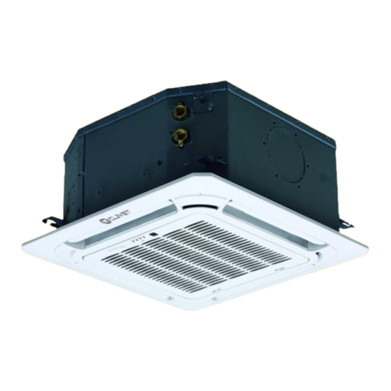
- Page 1 BOX 2 650x650 IB3-XY series from 27M to 53M...
- Page 2 Indicates that the appliance uses a flammable refrigerant. WARRANTY The product CLIVET is covered by a conventional warranty, valid from the date of purchase of the appliance, the conditions of which are specified in the GENERAL CONDITIONS OF SALE available at www.clivet.com WARNING –...
- Page 3 INDEX General Details ..........4 4 Maintenance ........... 23 General warnings and safety rules 4.1 Cleaning the indoor unit 1.2 Description of system components 4.2 Cleaning the air filter 1.3 Accessories 4.3 Cleaning the outdoor unit 1.4 Identification 4.4 Repairing refrigerant leaks 4.5 Extended periods of inactivity 2 Installation ............
- Page 4 WARNING – This manual is the property of CLIVET and reproduction or transfer to third parties of the contents of this document is prohibited. All rights reserved. It is an integral part of the product; make sure that it is always supplied with the appliance, even in case of sale/transfer to another owner, so that it can be consulted by the user or by personnel authorized to carry out maintenance and repairs.
- Page 5 General Details CAUTION DANGER – When connecting refrigerant piping,keep substances or gases other than the specified refrigerant from entering the unit. The presence of other gases or substances can reduce unit performance and cause an abnormal increase in pressure in the refrigeration cycle. This can lead to explosion hazards and resulting injuries. –...
- Page 6 General Details Description of system components Fig. 1 1 Drain pump (in the indoor unit) 5 Display LED 2 Drainage pipe 6 Front grille 3 Refrigerant piping 7 Air inlet 4 Ventilation slit 8 Air outlet WARNING The images in this manual are provided for illustrative purposes only. The appearance of your device may differ slightly from the illustrations shown here.
- Page 7 General Details Accessories The air conditioner is equipped with the following accessories. Use all specified installation components and accessories to install it. Incorrect installation may cause water leakage, electric shock and fire, or cause the unit to malfunction. Description Aspect Quantity Paper template for installation Indoor unit...
- Page 8 General Details Identification The indoor unit and the outdoor unit can be identified by the serial number label that shows the technical and performance data of the unit and what is required by the legislation in force. Serial number label Indoor unit Fig. 2 CAUTION...
- Page 9 Installation 2 INSTALLATION Installation - preliminary warnings WARNING Product receiving Before installing the indoor unit, consult the label on the product package to check that the The appliance is supplied packed in several parcels. model number matches the model number of Handling must be carried out by appropriate means in the outdoor unit.
- Page 10 Installation Indoor unit installation Refrigerant charge Minimum surface [kg] 32.8 2.4.1 Installation room 34.7 CAUTION 36.6 appliance must placed 38.5 well-ventilated room, with a minimum surface 7.956 40.1 area that varies according to the amount of refrigerant present. The following information can help you choose a suitable location for the indoor unit.
- Page 11 Installation It is PROHIBITED to install the indoor It is PROHIBITED to install the indoor unit in the following locations: unit in the following locations: – in a bathroom or laundry room, because – oil extraction drilling or fracking areas; excess humidity can reduce its service life –...
- Page 12 Installation 2.4.2 Hang the indoor unit 3 Hammer the ceiling hooks into the holes. Fasten the bolt with the washers and nuts provided. 1 Using the paper template provided, make a rectangular 4 Install the four suspension bolts. hole in the ceiling leaving a clearance of at least 1 m on all sides.
- Page 13 Installation NOTE FOR INSTALLATION IN NEW BUILDS Wall Main body 24mm Installation False ceiling Main body template M6 x 12 bolts Fig. 7 Fig. 9 CAUTION DANGER Check that the unit is completely horizontal. Incorrect installation can cause the drain pipe WARNING to go back into the unit or possible water leaks.
- Page 14 Installation 2.4.3 Preparation for connection pipes 2.4.4 Drainage pipe It is necessary to make a hole in the wall where the The drainage pipe is used to drain the water from the refrigerant piping, drainage pipe and electrical cables unit. Incorrect installation can cause damage to the unit that will connect the indoor unit to the outdoor unit will and other material damage.
- Page 15 Installation 1 Install the drainage pipe as shown in the figure: WARNING – When using an extension for the drainage pipe, tighten the connection on the inside 1-1.5 m with an additional protection pipe to stop it from coming loose. –...
- Page 16 Installation 2.4.5 Electrical connections Cables with the following characteristics are required for power supply and communication between the indoor and outdoor units: Power supplied Signal from outdoor from outdoor unit unit Indoor unit no.of cables/cross no.of cables/cross section section 2 x 1mm 2 x 1mm 2 x 1mm 2 x 1mm...
- Page 17 Installation REMOTE ON-OFF CAUTION DANGER For the input of the remote control terminal CN23 (ON-OFF) and the JR6 quick-release connector – DO NOT SWITCH LIVE AND NEUTRAL CABLES. Such a configuration is dangerous and may cause the air conditioner to malfunction. –...
- Page 18 Installation OUTDOOR AIR FAN – Holding the grille tilted at 45°, lift it slightly and detach it from the main body. For the input of terminal CN8 of the new outdoor air motor Fig. 19 Fig. 21 – Connect the fan motor to the input, regardless of the motor’s L/N;...
- Page 19 Installation 3 Assemble the intake grille. 5 Fasten the electrical panel cover with two screws. – Check that the hooks on the back of the grille fit correctly into the panel slot. Fig. 26 6 Close the intake grille and close the two hooks. Fig. 24 4 Connect the two decorative panel cables to the main unit board.
- Page 20 3 USE CAUTION DANGER – If an abnormal condition occurs (e.g. Description of system components there is a smell of burning), turn the unit off immediately and ask the dealer for assistance to avoid the risk of injury, fire or electrocution.
- Page 21 Manual operation (without remote Other functions control) – Default settings If the remote control does not work, the unit can be When the air conditioner restarts after a power operated manually with the manual control button failure, the factory default settings are restored located on the indoor unit.
- Page 22 Remote control MODE ON/OFF Presents the operating Unit switch-on/off button modes in the following order: AUTO » COOL » DRY » HEAT » FAN TEMP Increases the temperature by 1°C at a time. The maximum temperature is 30°C Used to select the fan speed TEMP from the following options: Reduces the temperature...
- Page 23 Maintenance 4 MAINTENANCE Cleaning the air filter The filter stops dust and other particles from entering the It is good practice to periodically clean both the internal indoor unit. A build-up of dust can reduce the efficiency and external parts of the appliance. This guarantees its of the air conditioner.
- Page 24 Maintenance Cleaning the outdoor unit 3 Detach the grille from the main unit by tilting it 45°, lifting it slightly and then pulling it forward. If the battery in the outdoor unit is clogged, remove the leaves and debris and then remove the dust with a jet of air or water.
- Page 25 Maintenance Extended periods of inactivity Maintenance at the start of the season If you do not plan to use the air conditioner for an extended period of time, proceed as follows: After a long period of non-use, or before a period of frequent use, proceed as follows: Clean all filters Activate the Ventilation mode...
- Page 26 Maintenance Troubleshooting CAUTION DANGER If any of the following conditions occur, turn the unit off immediately. – The power cable is damaged or unusually hot. – You can smell burning. – The unit makes loud or abnormal noises. – A fuse blows or the circuit breaker trips frequently. –...
- Page 27 Maintenance 4.7.2 Anomalies and remedies If problems occur, please check the following before contacting a service centre. Anomalies Possible causes Remedies The set temperature may be higher than Set a lower temperature the room temperature The heat exchanger of the indoor or Clean the heat exchanger (Service Centre) outdoor unit is dirty Remove the filter and clean it following...
- Page 28 Maintenance Error codes displayed on the indoor unit display Error code Cause Timer light EH 00 / Indoor unit EEPROM parameter error EH 0A EL 01 Indoor / outdoor unit communication error EH 03 The indoor fan speed is operating outside of the normal range(for some models) EH 60 Indoor room temperature sensor T1 is in open circuit or has short circuited EH 61...
- Page 29 Maintenance ERROR CODES DISPLAYED ON THE REMOTE CONTROL Use the “Query mode” function on the remote control to display the alarms (see: technical manual special modes). Error code Description EH 00 / Indoor unit EEPROM parameter error EH 0A EL 01 Indoor / outdoor unit communication error EH bA Communication error between indoor unit and indoor external fan module...
- Page 30 Maintenance PC 02 Top temperature protection of compressor or High temperature protection of IPM module PC 40 Communication error between outdoor main chip and compressor driven chip PC 41 Current Input detection protection PC 42 Compressor start error PC 43 Lack of phase (3 phase) protection PC 44 Outdoor unit zero speed protection...
- Page 31 Disposal 5 DISPOSAL The manufacturer is registered on the National EEE Register, Professional WEEE: all WEEE which comes from something in compliance with implementation of Directive 2012/19/EU other than private households. and pertinent national regulations on electrical and electronic This equipment may contain: equipment waste.
- Page 32 Attachments 6 ATTACHMENTS Indoor unit wiring diagrams...
- Page 33 EGALE APPRESENTANTE CLIVET S.P.A. - Via Camp Lonc, 25 - Z.I. VILLAPAIERA - 32030 FELTRE (BL) – ITALIA Cap. Soc. Eur 20.000.000 i.v. – C.F. e reg.Impr. BL n°.00708410253 – R.E.A. n°.66577 –P.I./ VAT :IT 00708410253 Tel. +39 0439 3131 - Fax +39 0439 313300 – Sito Web : www.clivet.it...
- Page 34 Attachments...
- Page 35 Attachments...
- Page 36 FOR 30 YEARS WE HAVE BEEN OFFERING SOLUTIONS FOR SUSTAINABLE COMFORT THE WELL-BEING OF PEOPLE AND THE ENVIRONMENT www.clivet.com sales and service CLIVET SPA Via Camp Lonc 25, Z.I. Villapaiera 32032 Feltre (BL) - Italy Tel. +39 0439 3131 - Fax +39 0439 313300 info@clivet.it...
Need help?
Do you have a question about the IB3-XY Series and is the answer not in the manual?
Questions and answers