Advertisement
Advertisement

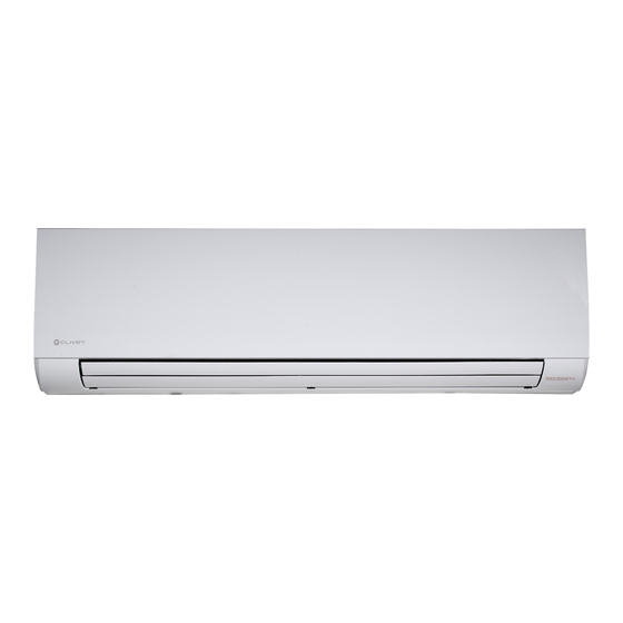
Summary of Contents for CLIVET CFW-2 1-5
- Page 1 Water terminal unit for installation, wall-mounted CFW-2 1-5...
- Page 2 , efficienc usage and finally disposal so tha em off...
- Page 3 Contents Installation manual .………………………………………………………………………… 5 Owner’s manual …………………………………...…………………………………………. Remote controller Owner’s manual …………………………………………………. To get complete and clear information, please also consider following issues Model identification Power supply Size 230V 1-phase 230V 1-phase 230V 1-phase 230V 1-phase 230V 1-phase...
- Page 5 Installation manual...
-
Page 7: Table Of Contents
PRECAUTIONS..................1 INSTALLATION INFORMATION............... 2 ATTACHED FITTINGS................3 INSPECTING AND HANDLING THE UNIT..........4 INDOOR UNIT INSTALLATION..............4 WATER PIPE INSTALLATION..............6 WIRING CHART..................6 1. PRECAUTIONS... -
Page 8: Installation Information
2. INSTALLATION INFORMATION... -
Page 9: Attached Fittings
3. ATTACHED FITTINGS 5 On / off input cable 6 0-10V input cable For connecting of of the fan speed 7 Modbus connection cable... -
Page 10: Inspecting And Handling The Unit
4. INSPECTING AND HANDLING THE UNIT 5. INDOOR UNIT INSTALLATION... -
Page 12: Water Pipe Installation
6. WATER PIPE INSTALLATION Water fittings Pipe Material Copper Pipe for Air Conditioner Model 42.5/51/68 85/102 Coil connections 3/4” 3/4” (flat plate) 3/4” 3/4” 1. Water inlet Ø 3/4" 2. Water outletØ 3/4" 3. Condensate drain Ø 20 mm... -
Page 13: Wiring Chart
7. WIRING CHART 0 0 ,25 0 0 ,38 0,50 1 1 5 5 1 1 5 5 0 0 ,02 0 0 ,02 0 0 ,02 0 0 ,02 0 0 ,02 0,20 0,20 0,30 0,30 0,40 220-240V~ 50Hz 0,75 >3 0,75... - Page 14 (MODBUS) ON/OFF OUTPUT Classes 0-10V input Fan speed 0< voltage < 3 PEMW00002 Alarm output 3< voltage < 5 signal cable 3 speed fan L=500mm 5< voltage < 7 7< voltage < 10 High...
- Page 15 manual...
- Page 17 1. IMPORTANT SAFETY INFORMATION...
- Page 18 3. OPERATION RANGE 2. PARTS NAMES 4. HINTS FOR ECONOMICAL OPERATION...
- Page 19 6. MAINTENANCE 5. ADJUSTING AIR FLOW DIRECTION...
- Page 20 7. FOLLOWING SYMPTOMS ARE NOT AIR CONDITIONER TROUBLES...
- Page 21 8. TROUBLESHOOTING 8.1. Troubles and causes of air conditioner 8.2. Troubles and causes of remote controller Operating LED (1 ) and Timer LED (2 Malfunction EEPROM communication error Can’t be recovery flash in 5Hz frequency Room temperature sensor Malfunction Timer LED (2 ) flash in 5Hz frequency probe abnormal Recover automatically after...
- Page 23 wner’s manual...
- Page 29 Decommissioning Disconnecting Only authorised personnel must disconnect the unit. Avoid leak or spills into the environment. Before disconnecting the unit, the following must be recovered, if present: • refrigerant gas • anti-freeze solutions in the water circuit Awaiting dismantling and disposal, the unit can also be stored outdoors, if the electrical, cooling and water circuits of the unit have 100% integrity and are isolated, bad weather and rapid change in temperature will not result in any environmental impact.
- Page 30 FOR OVER 30 YEARS, WE HAVE BEEN OFFERING SOLUTIONS TO ENSURE SUSTAINABLE COMFORT AND THE WELL- BEING OF PEOPLE AND THE ENVIRONMENT sales and assistance www.clivet.com...


Need help?
Do you have a question about the CFW-2 1-5 and is the answer not in the manual?
Questions and answers