Table of Contents
Advertisement
Quick Links
LK TapWater
DHW exchange controller
Installation
Operation
Functions and options
Troubleshooting
The Internet portal for easy and secure access to your system
data – www.vbus.net
Thank you for buying this product.
Please read this manual carefully to get the best performance from this unit. Please keep this manual safe.
Beginning with firmware version 2.0
en
Manual
Advertisement
Table of Contents

Related Manuals for LK TapWater


Summary of Contents for LK TapWater
- Page 1 LK TapWater Beginning with firmware version 2.0 DHW exchange controller Installation Operation Functions and options Troubleshooting The Internet portal for easy and secure access to your system data – www.vbus.net Thank you for buying this product. Please read this manual carefully to get the best performance from this unit. Please keep this manual safe.
-
Page 2: Safety Advice
Safety advice Information about the product Please pay attention to the following safety advice in order to avoid danger and Proper usage damage to people and property. The controller is designed for use in a DHW heat exchange module in compliance Danger of electric shock: with the technical data specified in this manual. -
Page 3: Description Of Symbols
Decommissioning Disconnect the device from the power supply. Dismount the device. Disposal • Dispose of the packaging in an environmentally sound manner. • At the end of its working life, the product must not be disposed of as urban waste. Old appliances must be disposed of by an authorised body in an environmentally sound manner. -
Page 4: Table Of Contents
Contents Overview ....................5 Hot water ...................24 Installation ...................6 Cascade ....................25 2.1 Mounting ........................6 Optional functions ................26 2.2 Electrical connection ....................6 10 Basic settings ..................31 2.3 Data communication / Bus..................7 11 MicroSD card ..................31 2.4 MicroSD card slot ......................7 12 User code ...................32 Operation and function ..............10 13 Manual mode ..................33 3.1 Buttons and adjustment dial ..................10... -
Page 5: Overview
Overview Technical data Inputs: 6 Pt1000 temperature sensors, • Customised control for systems with or without circulation 1 flow rate sensor (0-500 Hz interface) • Flexible circulation function for different user profiles, also available Outputs: 3 semiconductor relays, 2 PWM outputs, 1 potential-free extra-low with thermal disinfection voltage relay •... -
Page 6: Installation
Installation Note It must be possible to disconnect the device from the mains at any time. 2.1 Mounting Î Install the mains plug so that it is accessible at any time. Î If this is not possible, install a switch that can be accessed. WARNING! Electric shock! Upon opening the housing, live parts are exposed! -
Page 7: Data Communication / Bus
2.3 Data communication / Bus The controller is equipped with the VBus (21/22) for data transfer with and ener- ® 100 – 240 V~ gy supply to external modules. The connection is to be carried out at the terminals 50 – 60 Hz Made in Germany marked VBus (any polarity). -
Page 8: Overview Of Relay And Sensor Allocation
2.4.1 Overview of relay and sensor allocation Connection terminal Single station S1 (1 / 2) Flow primary circuit Single station S2 (3 / 4) S3 (5/ 6) Circulation S4 (7 / 8) Stratified return source S5 (9 / 10) Stratified return store DHW flow rate R4 (19 / 20) Error relay... - Page 9 Cascade R2 (station2) S3 (station1) R2 (station1) S5 (station 1) S4 (station 1) Connection terminal Station 1 Station 2 Station 3 / 4 S1 (1/2) Flow primary circuit Flow primary circuit Flow primary circuit S2 (3/4) S3 (5/6) Circulation S4 (7/8) Stratified return source S5 (9/10) Stratified return store...
-
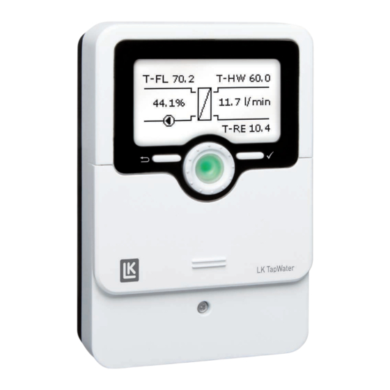
Page 10: Operation And Function
Operation and function 3.1 Buttons and adjustment dial 3.3 Operating control LED The controller is equipped with a multicolour operating control LED in the centre of the Lightwheel , indicating the following states: ® Colour Permanently shown Flashing Everything OK A note is available (see page 23), manual mode active Green... -
Page 11: Selecting Menu Points And Adjusting Values
3.5 Selecting menu points and adjusting values During normal operation of the controller, the display is in the main menu. If no button is pressed for 2 min, the display switches to standby mode. After further 10 s, the display illumination switches off. Î... -
Page 12: Adjusting The Timer
3.6 Adjusting the timer With the Timer time frames for the function can be adjusted. In the Day selection channel, the days of the week In order to save the time frame, select Save and are available. confirm the security enquiry with Yes. If several days are selected, they will be merged into one combination for the following steps. - Page 13 Copying a time frame: Changing a time frame: In order to copy time frames already adjusted into an- In order to change a time frame, proceed as follows: other day / other days, proceed as follows: Choose the days(s) into which the time frames are to be copied and select Copy from.
-
Page 14: Resetting The Timer
Resetting the timer: 3.7 Adjusting optional functions In order to reset time frames adjusted for a certain day, proceed as follows: Select the desired day. In the Optional functions menu, optional functions can be selected and adjusted. Select Reset and confirm the security enquiry with Yes. -
Page 15: Commissioning
Commissioning 4.1 Commissioning the single station When the hydraulic system is filled and ready for operation, connect the controller 1. Language: to the mains. Î Adjust the desired menu language. The controller runs an initialisation phase in which the Lightwheel glows green. - Page 16 6. Set hot water temperature: Î Adjust the desired set hot water temperature. 8. Stratified return: For further information, see page 24. Î Activate or deactivate the stratified return. Note The Thermal type requires the stratified re- turn source sensor S4. The Difference type 7.
-
Page 17: Commissioning The Cascade
4.2 Commissioning the cascade Station 1 is the cascade master, stations 2 to 4 are cascade slaves. The commis- 5. Date: sioning menu has to be run on each controller, beginning with the cascade master Î Adjust the date. First of all adjust the year, then the (station 1). - Page 18 8. Stratified return: 4.2.2 Cascade slaves Î Activate or deactivate the stratified return. 1. Language: For more information about the stratified return, see Î Adjust the desired menu language. page 29. Note The Thermal type requires the stratified re- 2. System type: turn source sensor S4.
-
Page 19: Main Menu
Main menu 5.1 Main menu Single station 5.2 Main menu Station 1 In this menu, different menu areas can be selected. In this menu, different menu areas can be selected. The following menus are available: The following menus are available in cascade operation: Status Status Hot water... -
Page 20: Menu Structure
5.3 Menu structure Main menu Status Status Hot water Overview Hot water T-HW set Optional functions Cascade* Cascade* Emergency operation Circulation Hot water Optional functions Disinfection Circulation Basic settings Stratified return Disinfection SD card Circulation Blocking protection Stratified return Type User code Error relay Error relay... -
Page 21: Status
Status The first part shows the primary circuit with the corresponding values. In the status menu of the controller, the status messages for every menu area can be found. Overview of displayed values Display Description T-store Store temperature stratified return Base / Centre Position of the valve stratified return T-RE... -
Page 22: Status / Overview Cascade
6.2 Status / Overview Cascade 6.3 Hot water The Status / Hot water menu indicates the status of the DHW heating. In the Status / Overview menu, all current measured values of the stations are indicated in a clear system graphic. 6.4 Cascade* Î... -
Page 23: Disinfection
6.6 Disinfection 6.9 Messages The Status / Disinfection menu indicates status information of the function. In the Status/Messages menu, error and warning messages are indicated. During normal operation, the message Everything OK is indicated. A line break or short circuit in a sensor line is indicated as !Sensor fault. In the 6.7 Stratified return case of an error, the LED of the Lighthweel ®... -
Page 24: Device Info
Hot water Message Category Cause / description !Stratified return Warning Failure Station 2 Different software variants used in the !Software update Warning cascade !Timeout Station 1 … 4 Warning No K-Bus signal available, station failure !Valve closed Warning No flow at the station !HW emerg. -
Page 25: Emergency Operation
Emergency operation Cascade Main menu / Hot water / Emerg. op. The Cascade menu is only available if the system type Station 1 has been se- This function can be used for ensuring the hot water supply in the case of a sen- lected. -
Page 26: Optional Functions
Optional functions In this menu, optional functions can be selected and adjusted. Circulation Example with a Grundfos Secondary circuit Direct Sensor Main menu / Opt. functions / Circulation Running an offset: Adjustment Adjustment range / Description Factory setting If the circulation was activated in the commissioning menu, the offset has already channel selection been carried out. - Page 27 Each variant has a timer by means of which time frames for the operation of the func- Circulation pump offset tion can be adjusted. Within the adjusted time frames the variants work as follows: When the hydraulic connection of the station has been established, carry out an offset.
- Page 28 Disinfection After disinfection has ended, the circulation pump remains switched on for the ad- justed overrun time. When the Disinfection function is active, it can be cancelled by means of the menu item Cancel? at ay time. WARNING! Scald danger! Scalding may occur if the set temperature is adjusted to a value higher than 60 °C.
- Page 29 Stratified return This function can be used for keeping the temperature stratification inside the store from being destroyed. For this function, 2 variants are available: Type Thermal: If the adjustable switch-on temperature is exceeded at the return sensor, the con- troller switches on the relay for the stratified return.
-
Page 30: Blocking Protection
Blocking protection Error relay Main menu / Opt. functions / Blocking protect. Main menu / Opt. functions / Error relay Adjustment Adjustment Adjustment Factory Description Adjustment range / selection Factory setting Description channel channel range / selection setting Error relay Activation of the function Yes, No B l o c k i n g... -
Page 31: Basic Settings
10 Basic settings 11 MicroSD card Main menu / Basic settings The controller is equipped with a MicroSD card slot for MicroSD memory cards. With a MicroSD card, the following functions can be carried out: Adjustment Description Adjustment range / selection Factory setting •... -
Page 32: User Code
Starting the logging Main menu / SD card Insert the MicroSD card into the slot. Adjustment channel Description Adjustment range / selection Factory setting Adjust the desired logging type and interval. Remove card... Safely remove card Logging will start immediately. Save adjustments Save adjustments Completing the logging process... -
Page 33: Manual Mode
13 Manual mode In this menu, the operating mode of all relays used can be adjusted. Auto Relay in automatic mode Pump running at adjusted speed (manual mode) 0 … 100 % Centre / Base Valve in adjusted position Open / Closed* Valve open or closed Error / OK Error relay in Error or OK mode... -
Page 34: Troubleshooting
14 Troubleshooting WARNING! Electric shock! Upon opening the housing, live parts are exposed! If a malfunction occurs, a message will appear on the display of the controller. Î Always disconnect the device from power supply be- fore opening the housing! The Lightwheel ®... - Page 35 Notes Pump noise can be heard, bubbling in the pipes. DHW heating does not work Controller in operation? System vented? Check the controller; Check the fuse of and the power supply to the controller. Vent the system. System vented? Vent the system. Draw-off amount is too small.
-
Page 36: Index
15 Index Blocking protection ......................30 Operating control LED ......................10 Operating mode, relays ......................33 Circulation ..........................26 Commissioning menu ......................15 Sensor fault, error message ....................23 Controller adjustments, loading of ..................32 Set hot water temperature ....................24 Stratified return ........................ - Page 40 LK Armatur AB LK Armatur Deutschland GmbH Distributed by: Garnisonsgatan 49 Alte Reichsstraße 15 SE-254 66 Helsingborg DE-32549 Bad Oeynhausen Sweden Deutschland © All contents of this document are protected by copyright.
Need help?
Do you have a question about the TapWater and is the answer not in the manual?
Questions and answers